Table of Contents
Advertisement
Quick Links
Advertisement
Table of Contents

Related Manuals for halstrup-walcher PS*3**DP series


Summary of Contents for halstrup-walcher PS*3**DP series
- Page 1 Instruction Manual PSx3xxDP halstrup-walcher GmbH Stegener Straße 10 D-79199 Kirchzarten, Germany Phone: +49 (0) 76 61/39 63–0 Fax: +49 (0) 76 61/39 63–99 E-Mail: info@halstrup-walcher.com Internet: www.halstrup-walcher.com Document 7100.003964 03/2017...
-
Page 2: Table Of Contents
PSx3xxDP Instruction Manual Table of Contents Purpose of instruction manual ..................5 Conformity .......................... 5 Safety precautions ......................6 Appropriate use ........................ 6 Shipping, assembly, electrical connections and start-up ........... 6 Troubleshooting, maintenance, repairs, disposal .............. 6 Symbols..........................7 Instrument description ...................... 8 Functions .......................... - Page 3 PSx3xxDP Instruction Manual 7.3.2 Release bit ........................17 7.3.3 Manual run release ..................... 17 7.3.4 Run with no reference loop ..................17 7.3.5 Set value for reference position ................... 17 7.3.6 Set and save reference position .................. 18 7.3.7 Accept and proceed to position ................... 18 7.3.8 Manual run, down......................
- Page 4 PSx3xxDP Instruction Manual Changing parameter values .................... 25 Backing up parameter data and the error memory ............26 Technical data ........................27 Drive speed and torque ....................27 Drive speed and torque PSE34xx ................... 28 Ambient conditions ......................29 Electrical data ......................... 29 Physical data ........................
-
Page 5: Purpose Of Instruction Manual
PSx3xxDP Instruction Manual Purpose of instruction manual This instruction manual describes the features of the PSx 3xxDP positioning systems and provides guidelines for their use. Improper use of these instruments or failure to follow these instructions may cause injury or equipment damage. All individuals responsible for operating these instruments must therefore be properly trained and aware of the hazards, and must carefully follow these operating instructions and the safety precautions detailed within. -
Page 6: Safety Precautions
PSx3xxDP Instruction Manual Safety precautions Appropriate use Positioning systems are especially suitable for automatically setting tools, stops or spindles for wood-processing equipment, packing lines, printing equipment, filling units and other types of special machines. PSx3xxDP positioning systems are not stand-alone instruments and may only be used if coupled to another machine. -
Page 7: Symbols
PSx3xxDP Instruction Manual Symbols The symbols given below are used throughout this manual to indicate instances when improper operation could result in the following hazards: WARNING! This warns you of a potential hazard that could lead to bodily injury up to and including death if the corresponding instructions are not followed. -
Page 8: Instrument Description
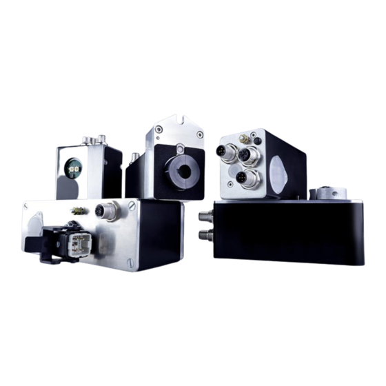
PSx3xxDP Instruction Manual Instrument description Functions The PSx3xxDP positioning system, an intelligent, compact, complete solution for positioning auxiliary and positioning axes, consists of an EC motor, gear power amplifier, control electronics, absolute measuring system and Profibus DP interface. The integrated absolute measuring system eliminates the need for a time-consuming reference run. -
Page 9: Pin Assignment
PSx3xxDP Instruction Manual Pin assignment For the supply voltage either a Binder series 713/763 (A-coded) round, 5-pin plug for PSE and PSS devices or a 5-pin Harting plug with protective sleeve (HAN4A) for the PSE34xx devices is located in the housing cover of the PSx3xxDP. A series 715 (B-coded) 5-pin round socket and 5-pin plug are provided for connecting the A Binder series 718 4-pin plug is used to connect the jog keys (optional). -
Page 10: Setting The Device Address And Terminating Resistors
PSx3xxDP Instruction Manual Setting the device address and terminating resistors Removing the protective cap provides access to two rotary switches for setting the device address and a DIP switch to set the terminating resistors. The rotary switches indicate the tens and ones places of the address selected. A setting of 01 is the delivery state;... -
Page 11: Using The Bus To Set The Address
DP address. The device address for all halstrup-walcher Instruments is 100 by default. If you wish to incorporate an address change into an SPS project and do not want to use 100, the address can be changed for a projected address. -
Page 12: Jog Key Operation
PSx3xxDP Instruction Manual Jog key operation Connecting the keyboard The jog keys attach to the instrument via the 4-pin connector. The switching contacts must be connected between +24V and the jog key inputs. Both GND cables must be connected if using an external power supply, making certain that the GND cable for the jog keys is linked to the control unit GND cable. -
Page 13: Start-Up
PSx3xxDP Instruction Manual Start-up Setting the reference position Once it has been installed, the PSx3xxDP must be moved to the reference position, either via the jog keys or with a positioning command. The ‘set reference position' command (see section entitled ‘Command byte configuration’) is used to set the internal position of the PSx3xxDP to zero. -
Page 14: Interface
PSx3xxDP Instruction Manual Interface Modules Format Meaning status byte 16 bit flags for instrument status actual signed long 32 bit current actual position in target-value increments position command 16 bit flags for controlling the instrument byte target signed long 32 bit next position to be achieved in target value position increments... -
Page 15: Motor Supply Voltage Ok
PSx3xxDP Instruction Manual 7.1.3 Motor supply voltage OK The power supply to the motor is higher than the value indicated in the ‘min. supply voltage’ parameter. This bit must be set prior to performing a run. The level of the supply voltage has a significant effect on the torque and/or motor speed. -
Page 16: Drag Error
PSx3xxDP Instruction Manual 7.1.10 Drag error If the load moment prevents the drive from achieving the target rpm, the current position will not agree with that for the target rpm, a situation that can cause problems when multiple drives are running in parallel. -
Page 17: Control Byte Configuration
PSx3xxDP Instruction Manual Control byte configuration Meaning 15(MSB) not assigned not assigned not assigned not assigned not assigned not assigned not assigned confirmation for hardware error release bit manual run release run with no reference loop set value for reference position set and save reference position accept and proceed to position manual run, down... -
Page 18: Set And Save Reference Position
PSx3xxDP Instruction Manual 7.3.6 Set and save reference position If this bit has been activated and the remaining bits in the command byte have not been set, the current position will be saved as the instrument’s new zero position. All positional data now use this point as a reference. -
Page 19: Direction Of Rotation
PSx3xxDP Instruction Manual Index Meaning Range of values Access 1 … 120.0% [0. 1%] target rpm, manual run 1 … 120.0% [0. 1%] max. rpm, left 1200 1 … 120.0% [0. 1%] max. rpm, right 1200 1 … 100.0% [0. 1%] max. -
Page 20: Direction Of Travel
PSx3xxDP Instruction Manual 7.5.2 Direction of travel If the length of the reference loop has been defined, this parameter establishes the direction in which the drive will approach the target position. If the direction of travel = 0, each position will be approached without a reference loop. -
Page 21: Max. Run Distance, Positive
PSx3xxDP Instruction Manual 7.5.8 Max. run distance, positive This parameter is used for setting the maximum run distance for positive rotation. Values should be entered as a % of the absolute run distance (256 rotations). The instrument checks to make certain that the sum of the maximum positive run distance and maximum negative run distance does not exceed 99.2%;... -
Page 22: Holding Torque
PSx3xxDP Instruction Manual 7.5.19 Holding torque For many applications, the drive requires a level of holding torque greater than the very low self- holding torque generated by the drive’s EC motor. This parameter allows the user to set that holding torque value. Current is then supplied to one of the motor windings when the drive is not operating. -
Page 23: Loop Length
PSx3xxDP Instruction Manual 7.5.26 Loop length The ‘direction of travel’ parameter can be used to instruct the drive to approach all positions from the same direction. If a positioning run is performed in the opposite direction, the drive will first move past its target and then perform a second positioning sequence, which takes it to the desired target position. -
Page 24: Device Type
PSx3xxDP Instruction Manual 7.5.35 Device type The device model is stored here as a hexidecimal figure. Format: xxxy (xxx = design and torque, y = diameter of the output shaft $E = 14 mm, 8 = 8 mm). 7.5.36 Software version This parameter contains the version number for the firmware stored on the instrument. -
Page 25: Changing Parameter Values
PSx3xxDP Instruction Manual 7.5.47 Error code This byte is used as a more precise diagnostic tool for troubleshooting a number of different errors, especially hardware errors. The meanings of individual bits are shown in the following table: Hexadec. Meaning learn mode active (for manufacturer’s use only) 15(MSB) 0x8000 0x4000... -
Page 26: Backing Up Parameter Data And The Error Memory
PSx3xxDP Instruction Manual Backing up parameter data and the error memory A special command allows the user to store parameter data in the EEPROM area, a process which does not affect the functioning of the instrument for the user. Every time the Profibus DP starts up, parameter data are reloaded through the bus, making saved data are irrelevant. -
Page 27: Technical Data
PSx3xxDP Instruction Manual Technical data Drive speed and torque drive model 301_8 302_8 305_8 322_14 325_14 PSE and PSS 301_14 302_14 305_14 311_8 312_8 315_8 311_14 312_14 332_14 335_14 nominal output torque (30 % OT) 1 Nm 2 Nm 5 Nm 2 Nm 5 Nm temporary breakaway torque... -
Page 28: Drive Speed And Torque Pse34Xx
PSx3xxDP Instruction Manual Drive speed and torque PSE34xx drive model PSE3410 PSE3418 PSE3430 nominal output torque (30 % OT) 10 Nm 18 Nm 30 Nm temporary breakaway torque ca.12,5Nm ca.22,5Nm ca.37,5Nm self-holding torque (w/ current) 5 Nm ca. 9 Nm ca.15 Nm positioning range 256 rotations... -
Page 29: Ambient Conditions
PSx3xxDP Instruction Manual Ambient conditions ambient temperature 0 °C to +45 °C storage temperature -10 °C to +70 °C shock resistance according to 50 g 11 ms DIN IEC 68-2-27 resistance to vibration 10 Hz to 55 Hz 1.5 mm according to DIN IEC 68-2-6 55 Hz to 1000 Hz 10 g 10 Hz to 2000 Hz 5 g... -
Page 30: Physical Data
PSx3xxDP Instruction Manual Physical data positioning range 250 usable rotations, no mechanical limits measuring system has a span of 256 turns, minus 3 turns security stock at upper and lower range limit torsional rigidity max. 0.2° (angle of rotation when switching from operation without backlash to maximum torque) gear backlash... - Page 31 PSx3xxDP Instruction Manual...
Need help?
Do you have a question about the PS*3**DP series and is the answer not in the manual?
Questions and answers