
Subscribe to Our Youtube Channel
Related Manuals for NetterVibration NEA Series

Summary of Contents for NetterVibration NEA Series
- Page 1 March 2021 Operating instructions for No. 1929E Netter electric external vibrators Page 1/35 Series NEA/NEG/NEG S/NES These operating instructions apply to: Series NEA Series NEG Series NEG S Series NES...
-
Page 2: Table Of Contents
Contents General information Safety Technical data Design and function Transport and storage Installation Start-up and operation Maintenance and servicing Troubleshooting Spare parts and accessories Disposal Please refer to the delivery note for the scope of delivery. Scope of delivery Check the packaging for possible transport damage. In the event of damage to the packaging, check the contents for completeness and possible damage. -
Page 3: General Information
General information General information Before installing the NEA/NEG read these instructions carefully. It is the Use and basis for any action when dealing with the NEA/NEG, and may be used for storage training purposes. The instructions should be subsequently stored at the operation site. - Page 4 General information NEA/NEG from housing size 100 upwards are suitable for use in potential- ly explosive areas of the category 2D in the zone 21 and 22. In particular the standards DIN EN IEC 60079-0 and DIN EN 60079-31 (IEC 60079-31) are observed. Before using the NEA/NEG the operator must exclude the possibility that the introduction of vibrational energy poses the risk of explosion.
- Page 5 General information Notes IMPORTANT indicates actions, methods or notes that are not relative to safety, e.g. use- ful information and tips. Environmentally safe disposal indicates the obligation of environmentally safe disposal. Explosion prevention indicates information on explosion prevention. When operating the NEA/NEG in potentially explosive areas all notes, ATEX-notes marked with the Ex-symbol , must be observed.
-
Page 6: Safety
Safety Safety The NEA/NEG are intended for generating circular vibrations. Intended use General applications are: loosening, conveying, sorting, compacting, sepa- rating bulk materials and reducing friction. NEA/NEG are used for empty- ing bunkers, as drives for conveyor troughs, sieves and vibrating tables. The NEA/NEG are designed for installation in machines and may only be put into operation, if it has been assured that the complete machine com- plies with the regulations of the machinery directive. - Page 7 Safety High voltage DANGER Risk of electric shock due to high voltage An electric shock leads to serious injuries or even death. ➢ Observe the permissible protection class and earthing. The NEA/NEG may only be operated with the correct connection of the protective conductor. ➢...
- Page 8 Safety Spark WARNING formation Spark formation The impact of corroded steel parts on the aluminium hous- ing at high speed can cause spark formation and thus lead to an explosion. ➢ Choose the installation position carefully, so that there are no external impacts. ➢...
- Page 9 Safety Hot surface WARNING Hot surface If the permissible operating conditions and the maintenance requirements are not observed or if the vibrator does not fit the application, the housing surface may become very hot. In Ex-zones there is a risk of ignition of an explosive atmos- phere due to hot surfaces.
- Page 10 Safety Falling parts WARNING Falling parts The NEA/NEG or parts of the construction can come loose due to vibra- tion. Falling parts can lead to severe personal injuries. ➢ Use only suitable fastening screws and safety washer to attach the NEA/NEG.
-
Page 11: Technical Data
The sound level is determined to a great extent by the surface upon which the NEA/NEG is mounted (e.g. sheet metal). The sound level will be amplified by non-silenced sheet metal. * Higher temperatures are only possible after consultation with and written approval from the application techni- cians of NetterVibration. - Page 12 Technical data type designation Type plate for rotary speed housing sizes nominal voltage 50 and 60 current phases serial number year of manufacture / de- gree of protection insulation class power nominal frequency centrifugal force duty cycle ATEX certification type designation Type plate nominal voltage from housing...
-
Page 13: Design And Function
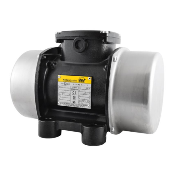
Design and function Design and function Example: NEG 501140 Example: NEG 50120 Design Element Function Contains and protects the components of the Housing NEA/NEG. Unbalance covers Protect against grabbing into the unbalances. Housing foot Attach the NEA/NEG to the mounting surface. Type plate Shows model specific information and data. -
Page 14: Transport And Storage
Transport and storage Transport and storage Observe the safety instructions in Ch. Safety, from page 6 on. Please refer to the brochure for weights and dimensions. When transporting the NEA/NEG, ensure that the NEA/NEG is not sub- Transport- jected to strong impacts or vibrations that could damage the bearings. conditions Please observe the following notes: •... -
Page 15: Installation
Installation Installation Observe the safety instructions in Ch. Safety, from page 6 on. Please refer to the brochure for weights and dimensions. Important: For NEA/NEG with housing size 101 to 120 the terminal box is Fastening integrated in the housing foot. These vibrators must be electrically con- the NEA/NEG nected before fastening. - Page 16 Installation Electrical The following requirements and conditions must be met to connect the connection NEA/NEG electrically: • The permissible operating conditions must be met. Please refer to chap. Technical data, page 11 for operating conditions. • A suitable overload protection (1) must be pre-connected to each vibrator.
- Page 17 Installation • The electrical parameters U, I, P on the type plate must be ob- served. • Tighten terminal plate nuts with pre- scribed torque, see chap. Technical da- ta, from page 11. Remember to put the safety washer between the ring and the nut and the vibration-damping insert back.
- Page 18 Installation Connection diagram Series NEG / 3-phase current Smaller voltage Higher voltage 1: Earthing terminal for protective conduc- 1: Earthing terminal for protective conduc- 2: PTC-Thermistor connection (depending 2: PTC-Thermistor connection (depending on the type) on the type) Connect the NEA according to the type plate: Connection examples NEA capacitor box...
-
Page 19: Start-Up And Operation
Start-up and operation Start-up and operation Observe the safety instructions in chap. Safety, from page 6 on. Please refer to chap. Technical data, page 11 for permissible operating Permissible conditions. operating conditions • When commissioning the NEA/NEG, the rules and regulations of the Regulations local associations for electrical engineering (e.g. - Page 20 Start-up and operation Check that the cables are undamaged and laid according to the known regulations and standards. Check that all permissible operating conditions have been observed. Check that all protective measures on the system have been ob- served. Eliminate possible errors before start-up. Screw connections must be checked and, if necessary, retightened after 1 h operating time (after initial start-up) and thereafter regularly (generally monthly).
- Page 21 Start-up and operation Procedure: Switch off the NEA/NEG at the main switch, secure against uninten- tional starting and ensure that there is no voltage. Loosen both unbalance covers. Loosen the locking nuts or locking screws. Bring the unbalances to the desired setting according to the following descriptions for the various unbalance discs.
- Page 22 Start-up and operation Type: Unbalance Type: Unbalances Type Quantity Type Quantity 50 Hz 60 Hz 50 Hz 60 Hz 2530 162110 2570 162550 25210 163030 25420 163820 25540 164700 25700 165190 25930 166270 251410 166670 251800 167890 252060 168500 252370 169510 253050 1612060...
- Page 23 Start-up and operation Unbalance The centrifugal force is adjustable with the unbalance discs (lamella) of discs type XL in the following steps: type XL 1: Number of unbalance discs per side 2: Default number of unbalance discs per vibrator 3: Centrifugal force in % There are 2 possibilities to adjust the unbalances: The unbalance adjustment (fine adjustment) is carried out by remov- ing one unbalance disc on each side.
- Page 24 Start-up and operation Unbalances The centrifugal force is adjustable with the unbalance discs (lamella) type type XLs XLs. Adjustment of the unbalances is carried out according to a scale disc or the supplementary sheet in the terminal box of the NEA/NEG. By rotating the outer, adjustable unbalance disc(s) to another position, the percentage of the centrifugal force changes as shown in the illustration below.
- Page 25 Start-up and operation Example: NEG 50120 / 50 Hz has a total of 6 unbalance discs (3 discs per side: 2 fixed, 1 adjustable). If a centrifugal force of 88% is desired, the adjustable unbalance discs are rotated anticlockwise on both sides into the fourth grid position. centrifugal force 100 % centrifugal force 88 % Unbalances...
-
Page 26: Maintenance And Servicing
Maintenance and servicing Maintenance and servicing Observe the safety instructions in chap. Safety, from page 6 on. Information regarding tightening torques for screws and nuts can be found Technical data in Ch. Technical data, page 11. Expertise and Maintenance and servicing of the vibrators may only be performed by reg- regulations ularly trained, authorised and qualified personnel. - Page 27 Maintenance and servicing Interval Action Monthly Check screw connections and retighten if necessary. Check ball or roller bearings and relubricate if necessary, see section "lubrication". Damaged bearings or bearings whose service life has been reached, must be replaced immediately. Check cable supply line. Every 6 month Check proper condition of connecting cables and plugs.
- Page 28 Maintenance and servicing Lubrication / Type of lubrication or grease quantity of the bearings and bearing life of bearing life the NEG: Type Lubrication/ Bearing Bearing Type Lubrication/ Bearing Bearing grease life [h] life [h] grease life [h] life [h] quantity [g] 50 Hz 60 Hz...
- Page 29 Maintenance and servicing Type Lubrication/ Bearing Bearing Type Lubrication/ Bearing Bearing grease life [h] life [h] grease life [h] life [h] quantity [g] 50 Hz 60 Hz quantity [g] 50 Hz 60 Hz 12100 > 100,000 > 100,000 122920 > 100,000 43,076 12180 >...
- Page 30 Maintenance and servicing Switch off NEA/NEG, secure against switching on again and ensure that it is volt-free. Loosen screw (24) and remove unbalance covers (23). Disassemble unbalances type XS: After removing the circlip (20) and loosen- ing the clamping screws (16), the unbal- ances can be removed.
-
Page 31: Troubleshooting
Troubleshooting Troubleshooting Observe the safety instructions in chap. Safety, from page 6 on. Troubleshooting of the vibrators may only be performed by regularly Expertise and trained, authorised and qualified personnel. Work on the electrical system regulations may only be carried out by a qualified electrician. The qualified personnel has to work exclusively with tools suitable for the application. - Page 32 Troubleshooting Fault Possible cause Corrective action Excessive heating Wiring wrong / overload Check circuit diagram. of the vibrator Check mains voltage and cable cross- Mains voltage too low section and, if necessary, adjust or replace cable. Too much grease in bearings Fill in correct amount of grease.
-
Page 33: Spare Parts And Accessories
Spare parts and accessories 10 Spare parts and accessories Please provide the following details when ordering spare parts: Ordering of spare parts • type designation according to the type plate • serial number according to the type plate • description and position number of spare part •... - Page 34 Spare parts and accessories Accessories The following accessories are available for NEA/NEG: Component Description Shim washers Compensation for removed unbalance discs. CC-unbalances Depending on the direction of rotation, two different unbalances can be achieved. Fastening kits NBS Recommended for secure and permanent fastening of the NEA/NEG.
-
Page 35: Disposal
Disposal 11 Disposal Prices All parts of the NEA/NEG must be properly disposed of accord- ing to the material specifications. The valid disposal prices of the NEA/NEG are available on request. All parts of the NEA/NEG can be recycled. Material- specifications Type: NEA Material...
Need help?
Do you have a question about the NEA Series and is the answer not in the manual?
Questions and answers