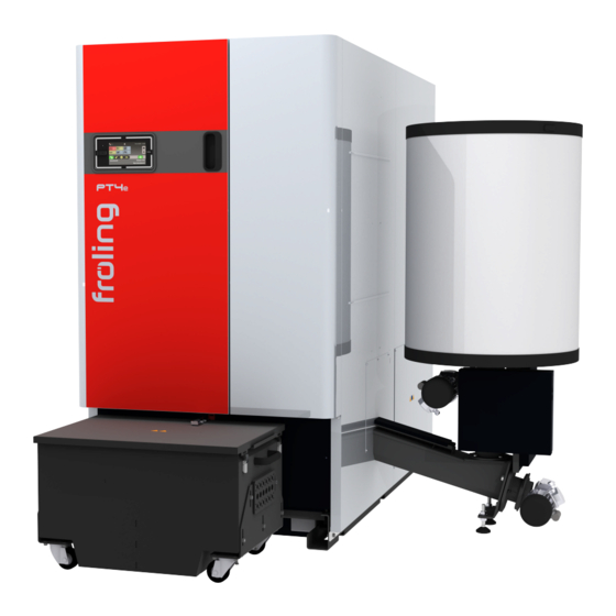
Fröling PT4e 200 Installation Instructions Manual
Pellet boiler
Hide thumbs
Also See for PT4e 200:
- Original installation instructions (68 pages) ,
- Service handbook (116 pages) ,
- Installation instructions manual (80 pages)
Table of Contents
Advertisement
Quick Links
Installation Instructions
Pellet boiler PT4e 200-250
Translation of the original German installation instructions for technicians
Read and follow the instructions and safety information!
Technical changes, typographical errors and omissions reserved!
M2280120_en | Edition 06/03/2020
Fröling GesmbH | A-4710 Grieskirchen, Industriestraße 12 | www.froeling.com
Advertisement
Table of Contents

Related Manuals for Fröling PT4e 200


Summary of Contents for Fröling PT4e 200
- Page 1 Installation Instructions Pellet boiler PT4e 200-250 Translation of the original German installation instructions for technicians Read and follow the instructions and safety information! Technical changes, typographical errors and omissions reserved! M2280120_en | Edition 06/03/2020 Fröling GesmbH | A-4710 Grieskirchen, Industriestraße 12 | www.froeling.com...
-
Page 2: Table Of Contents
Measuring port Boiler ventilation Technology Dimensions Components and connections External suction module Technical data 4.4.1 PT4e 200 - 250 4.4.2 Boiler data for planning the flue gas system Assembly Materials supplied Transport Positioning Temporary storage Setting up in the boiler room 5.5.1... - Page 3 Before commissioning / configuring the boiler Initial startup 6.2.1 Permitted fuels Wood pellets 6.2.2 Non-permitted fuels Decommissioning Mothballing Disassembly Disposal Notes Appendix Addresses 9.1.1 Address of manufacturer Customer service 9.1.2 Address of the installer Installation Instructions PT4e 200-250 | M2280120_en...
-
Page 4: General
General 1 General Thank you for choosing a quality product from Froling. The product features a state-of- the-art design and conforms to all currently applicable standards and testing guidelines. Please read and observe the documentation provided and always keep it close to the system for reference. -
Page 5: Safety
The dangerous situation may occur and if measures are not observed it will lead to minor injuries. NOTICE The dangerous situation may occur and if measures are not observed it will lead to damage to property or pollution. Installation Instructions PT4e 200-250 | M2280120_en... -
Page 6: Qualification Of Assembly Staff
Safety Qualification of assembly staff 2.2 Qualification of assembly staff CAUTION Assembly and installation by unqualified persons: Risk of personal injury and damage to property During assembly and installation: ❒ Observe the instructions and information in the manuals ❒ Only allow appropriately qualified personnel to work on the system Assembly, installation, initial startup and servicing must always be carried out by qualified personnel: - Heating technician / building technician... -
Page 7: Design Information
ÖNORM H 5195-1 Prevention of damage by corrosion and scale formation in closed warm water heating systems at operating temperatures up to 100°C (Austria). VDI 2035 Prevention of damage hot water heating systems (Germany) Installation Instructions PT4e 200-250 | M2280120_en... -
Page 8: Regulations And Standards For Permitted Fuels
Design Information Notes on standards SWKI BT 102-01 Water quality for heating, steam, cooling and air conditioning systems (Switzerland) UNI 8065 Technical standard regulating hot water preparation. DM 26.06.2015 (Ministerial Decree specifying the minimum requirements) Follow the instructions of this standard and any related updates. (Italy) 3.1.4 Regulations and standards for permitted fuels 1. -
Page 9: Installation And Approval Of The Heating System
(e.g. chlorination units for swimming pools). ▪ Keep the air suction opening of the boiler free of dust. ▪ The system must be protected against the chewing or nesting of animals (e.g. rodents etc.). Installation Instructions PT4e 200-250 | M2280120_en... -
Page 10: Requirements For Central Heating Water
Design Information General information for installation room (boiler room) Ventilation of the boiler room Ventilation air for the boiler room should be taken from and expelled directly outside, and the openings and air ducts should be designed to prevent weather conditions (foliage, snowdrifts, etc.) from obstructing the air flow. -
Page 11: Notes For Using Pressure Maintenance Systems
If the pressure is too high, air is released by means of a solenoid valve. The systems are built solely with closed-diaphragm expansion tanks to prevent the damaging introduction of oxygen into the heating water. Installation Instructions PT4e 200-250 | M2280120_en... -
Page 12: Return Temperature Control
Design Information Return temperature control Pump-controlled pressure maintenance A pump-controlled pressure maintenance unit essentially consists of a pressure- maintenance pump, relief valve and an unpressurised receiving tank. The valve releases hot water into the receiving tank if the pressure is too high. If the pressure drops below a preset value, the pump draws water from the receiving tank and feeds it back into the heating system. -
Page 13: Chimney Connection/Chimney System
The diameter of the measuring probe used by Froling customer service is 14 mm. To avoid measuring errors due to the ingress of false air, the diameter of the measuring port must not exceed 21 mm. Installation Instructions PT4e 200-250 | M2280120_en... -
Page 14: Boiler Ventilation
Design Information Boiler ventilation 3.9 Boiler ventilation ❒ Fit the automatic ventilating valve at the highest point on the boiler or at the ventilation connection (if present). ➥ This ensures that air in the boiler is constantly expelled, thus preventing malfunctions caused by air in the boiler ❒... -
Page 15: Technology
2005 Total length incl. ash container 2550 Length, back of boiler to stoker 1310 connection Length of particle separator (optional) 1. Value can be increased by 40 mm (max.) by adjusting the adjustable foot Installation Instructions PT4e 200-250 | M2280120_en... - Page 16 Technology Dimensions PT4e 200-250 Item Description 200-250 Height, flow connection 1770 Height of rear flue gas pipe 1350 connection (optional) Height, return connection with 1240 integrated return feed boost Height, drainage connection Height, safety heat exchanger 1720 connection Clearance flue gas pipe connection...
-
Page 17: Components And Connections
249 mm (optional) Boiler return 2 ½“ Mixing valve for the return temperature control Pump for the return temperature WILO Stratos Para 30/1-8 control Line regulating valve (optional) Drainage 1“ Ash container 160 Litres Installation Instructions PT4e 200-250 | M2280120_en... -
Page 18: External Suction Module
Technology External suction module 4.3 External suction module Measur Description Unit Size 1 Size 2 ement Width of suction module Length of suction module Height of suction module Total height incl. hose connection Return-air line connection (line to suction point) Return-air line connection (line to boiler) Fröling GesmbH | A-4710 Grieskirchen, Industriestraße 12 | www.froeling.com... -
Page 19: Technical Data
1. Emissions of particulate matter, organic gaseous compounds, carbon monoxide and nitrogen oxides shall be expressed standardised to a dry flue gas basis at 10 % oxygen and standard conditions at 0°C and 1013 millibar Installation Instructions PT4e 200-250 | M2280120_en... -
Page 20: Boiler Data For Planning The Flue Gas System
Technology Technical data 4.4.2 Boiler data for planning the flue gas system Description PT4e Flue gas temperature at nominal load °C Flue gas temperature at partial load - volume concentration at nominal load / partial load 12.3 / 11.3 12.8 / 11.8 Flue gas mass flow at nominal load kg/h kg/s... -
Page 21: Assembly
Possibility of damage to components if handled incorrectly ❒ Follow the transport instructions on the packaging ❒ Transport components with care to avoid damage ❒ Protect components against damp ❒ Pay attention to the pallet's centre of gravity when lifting Installation Instructions PT4e 200-250 | M2280120_en... -
Page 22: Positioning
Assembly Positioning 5.3 Positioning ❒ Position a forklift or similar lifting device at the boiler base and bring in the components If you need to dismantle the boiler to bring it in: ❒ Remove cardboard and transport frame ⇨ See "Remove cardboard and transport frame" [page 23] ❒... -
Page 23: Temporary Storage
❒ Position a forklift or similar lifting device with a suitable load-bearing capacity at the base frame ❒ Lift and transport to the intended position in the installation room. ➥ Pay attention to the operating and maintenance areas of the equipment in the process! Installation Instructions PT4e 200-250 | M2280120_en... -
Page 24: Operating And Maintenance Areas Of The Equipment
▪ Observe the applicable standards and regulations when setting up the system. ▪ Observe additional standards for noise protection! (ÖNORM H 5190 - Noise protection measures) PT4e 200-250 900 mm 300 mm 500 mm... -
Page 25: Dismantling For Location Where Positioning Is Difficult
❒ Remove the small cover plate on the hinge of the right insulated door ❒ Remove the control cover on the left insulated door ❒ Unplug both connectors on the control ❒ Remove both insulated doors Installation Instructions PT4e 200-250 | M2280120_en... - Page 26 Assembly Dismantling for location where positioning is difficult ❒ Unplug the connector for the ignition and the stoker drive from the wood chip module ❒ Pull the cable out of the cable duct in the controller box ➥ Cables can remain in the cable duct on the side panel ❒...
- Page 27 980 mm 2210 mm NOTICE! Assemble all components in reverse order. Connect the glow igniter plug on the wood chip module to the “ELECTRICAL IGNITION” position and the stoker drive to the “STOKER SCREW” position. Installation Instructions PT4e 200-250 | M2280120_en...
-
Page 28: Assembly Work
Assembly Assembly work 5.7 Assembly work 5.7.1 Levelling the boiler ❒ Lift the boiler using an appropriate lifting device ❒ Position a Sylomer pad under the boiler base ➥ Sylomer pads prevent the transmission of noise to the ground ❒ Carefully release the lifting device and check that the boiler is level ❒... - Page 29 ❒ Hang the control cabinet on the screw heads and tighten the screws ❒ Position the thermal insulation on the stoke flange ❒ Position the thermal insulation panels on the stoker as shown ❒ Wrap thermal insulation around the stoker duct Installation Instructions PT4e 200-250 | M2280120_en...
- Page 30 Assembly Assembly work ❒ Remove the cover on the cable duct and lay the cables of the components via the side panel to the control cabinet of the boiler ⇨ See "Connect the suction unit components" [page 39] ❒ Loosen both screws below the cable duct on the stoker ❒...
-
Page 31: Control The Return Temperature Control
❒ Slide the ash container onto the boiler and attach using clamping lever ❒ Loosen the screw connection and adjust castors to the ground ❒ Horizontally align the ash container and attach the screw connection ❒ Remove the ash container and spacer plate Installation Instructions PT4e 200-250 | M2280120_en... -
Page 32: Install The Line Regulating Valve
Assembly Assembly work 5.7.5 Install the line regulating valve ❒ Remove the rear cover plate on the return as well as the cover plate underneath ❒ Remove both pipe sections and ball valves, seal line regulating valve instead ➥ IMPORTANT: Pay attention to direction of flow. The arrow (A) must point downward. -
Page 33: Installing The External Suction Module
➥ If the suction module is positioned at a maximum distance of 2 m to the boiler, the power supply line can be plugged in as is. When distances are greater the power supply line must be lengthened accordingly on-site Installation Instructions PT4e 200-250 | M2280120_en... - Page 34 Assembly Assembly work ❒ Unwind the cable of the suction turbine and feed it through the opening of the housing underside ❒ Remove the protective cap on the underside of the suction module ❒ Lay the return air line from the suction point to the suction module and fix it to the pressure side (position 1) with a hose clamp ❒...
-
Page 35: Assembly Information For Hose Lines
▪ The return-air line can be made up of several sections, but consistent potential equalisation must be established throughout the line. ▪ For systems starting at 48 kW, only suction hoses with PU inlets are recommended due to the increased load. Installation Instructions PT4e 200-250 | M2280120_en... -
Page 36: Potential Equalisation
Assembly Assembly work Potential equalisation When connecting the hose lines to the individual connections, ensure there is consistent potential equalisation throughout the line. ❒ Expose approximately 8 cm of the earth wire at the end of the hose line ➥ TIP: Slit the insulation open along the wire with a knife ❒... -
Page 37: Hydraulic Connection
▪ Its size must comply with the design information in EN 12828 - Appendix D ▪ Ideally it should be installed in the return line. Follow the manufacturer’s installation instructions We recommend installing some sort of control device (e.g. thermometer) Installation Instructions PT4e 200-250 | M2280120_en... -
Page 38: Electrical Connection
Assembly Electrical connection 5.9 Electrical connection DANGER When working on electrical components: Risk of electrocution! When work is carried out on electrical components: ❒ Always have work carried out by a qualified electrician ❒ Observe the applicable standards and regulations ➥... -
Page 39: Connect The Suction Unit Components
❒ Route the power supply from the boiler controller to the control cabinet of the suction system ➥ Flexible sheathed cable must be used for the wiring; this must be of the correct size to comply with applicable regional standards and regulations Installation Instructions PT4e 200-250 | M2280120_en... -
Page 40: Connect The Suction Turbine
Assembly Electrical connection Connect the suction turbine 7 9 11 13 15 17 19 2 PE 4 PE 6 PE 8 10 12 14 16 18 PE 3 ... L 4 ... N GND ... PE ❒ Connect the suction turbine supply in the control cabinet of the suction system Connect the fill level sensors 7 9 11 13 15 17 19... -
Page 41: Connect Sensor Of The Stoker Monitoring
❒ Connect sensor of the stoker monitoring to the "Sensor 2” position on the core module in the boiler controller Check the digital module ❒ Set the module address of the digital module to “3” Installation Instructions PT4e 200-250 | M2280120_en... -
Page 42: Mains Connection
Assembly Electrical connection 5.9.3 Mains connection At the back of the boiler: ❒ Press the mains plug to release it and remove ❒ Open the plug and connect the mains connection cable ➥ Flexible sheathed cable must be used for the wiring; this must be of the correct size to comply with applicable regional standards and regulations. -
Page 43: Connecting The Discharge System
8 10 12 14 16 18 PE 5 ... L 6 ... N GND ... PE ❒ Lay the cable of the shaker to the control cabinet of the suction system and connect it according to the circuit diagram Installation Instructions PT4e 200-250 | M2280120_en... -
Page 44: Pellet Mole
Assembly Electrical connection pellet mole 7 9 11 13 15 17 19 2 PE 4 PE 6 PE 8 10 12 14 16 18 PE 5 ... L 6 ... N GND ... PE ❒ Lay the cable of the pellet mole to the control cabinet of the suction system and connect it according to the circuit diagram 1-2-3 suction module 7 9 11... - Page 45 8, 12, 16 ... L 10, 14, 18 ... N ... PE ❒ Lay the cables of the shaker units to the control cabinet of the suction system and connect them according to the circuit diagram Installation Instructions PT4e 200-250 | M2280120_en...
-
Page 46: Pellet Suction Screw Dm 80
Assembly Electrical connection Pellet suction screw DM 80 When using more than one DM 80 pellet suction screw in conjunction with the 1-2-3 suction module, an additional Froling feed system module is required. The following schematic diagram shows the electrical connection of the discharges. All connection work can be found in the enclosed installation and operating instructions for the feed system module. - Page 47 19, 22, 25 ... VF 2 GND 20, 23, 26 ... VF 2 RF 2 21, 24, 27 ... RF 2 ❒ Connect the connection line for the motor control to the 4-pole plugs of the change-over units used Installation Instructions PT4e 200-250 | M2280120_en...
-
Page 48: Configuring The Discharge System In The Software
Assembly Electrical connection Configuring the discharge system in the software In the software, navigate to the “Discharge” menu. Feed system System menu System System selection In the “Discharge” menu, select the “Feed system configurator” and enter the number “8” for the configuration (corresponds to the pellet suction system PT4e, cf. -
Page 49: Final Installation Steps
❒ Put on insulating cover with thermal insulation ➥ T4e 200-250: two insulated covers ➥ T4e 300-350: three insulated covers ❒ Slide the floor insulation underneath the boiler from the front and back as shown Installation Instructions PT4e 200-250 | M2280120_en... - Page 50 Assembly Final installation steps ❒ Slide the ash container onto the ash duct and secure with the locking lever (A) ❒ Slide the key plate (B) into the safety limit switch and close both insulated doors The safety limit switch can be adapted to the ash container as necessary: ❒...
-
Page 51: Start-Up
❒ Check that the drives and servo motors are working and turning in the right direction. NOTICE! Check the digital and analogue inputs and outputs - See the instruction manual for the boiler controller. Installation Instructions PT4e 200-250 | M2280120_en... -
Page 52: Initial Startup
Start-up Initial startup 6.2 Initial startup 6.2.1 Permitted fuels Wood pellets Wood pellets made from natural wood with a diameter of 6 mm Note on standards Fuel acc. to EN ISO 17225 - Part 2: Wood pellets class A1 / D06 plus / DIN plus certification scheme and/or: General note:... -
Page 53: Decommissioning
(e.g. AWG in Austria) ❒ You can separate and clean recyclable materials and send them to a recycling centre. ❒ The combustion chamber must be disposed of as builders' waste. Installation Instructions PT4e 200-250 | M2280120_en... -
Page 54: Notes
Notes 8 Notes Fröling GesmbH | A-4710 Grieskirchen, Industriestraße 12 | www.froeling.com... - Page 55 Notes Installation Instructions PT4e 200-250 | M2280120_en...
-
Page 56: Appendix Addresses
Appendix Addresses 9 Appendix 9.1 Addresses 9.1.1 Address of manufacturer FRÖLING Heizkessel- und Behälterbau GesmbH Industriestraße 12 A-4710 Grieskirchen AUSTRIA TEL 0043 (0)7248 606 0 FAX 0043 (0)7248 606 600 EMAIL info@froeling.com INTERNET www.froeling.com Customer service Austria 0043 (0)7248 606 7000 Germany 0049 (0)89 927 926 400 Worldwide...
Need help?
Do you have a question about the PT4e 200 and is the answer not in the manual?
Questions and answers