Table of Contents
Advertisement
Quick Links
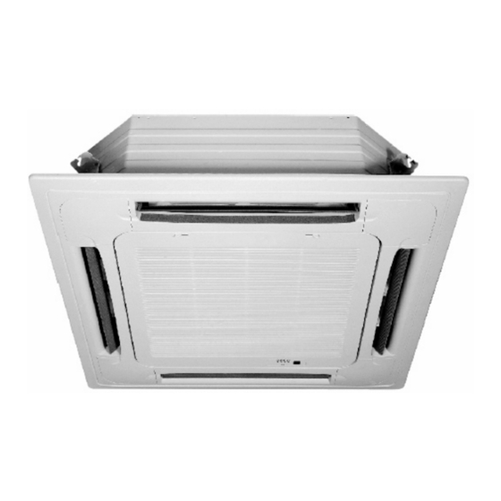
MODELS
4-way blow ceiling mounted cassette
KXV 021
KXV 030
KXV 024
KXV 036
SAFETY PRECAUTIONS
● Read the following "SAFETY PRECAUTIONS" carefully before installation.
● Carry out test running to confirm that no abnormality occurs after the installation. Then, explain to user the operation, care and maintenance as
stated in instructions. Please remind the customer to keep the operating instructions for future reference.
WARNING
This indication shows the possibility of causing death or serious injury.
CAUTION
This indication shows the possibility of causing harm or damage the equipment.
1) Use qualified installer and follow carefully this instructions. Otherwise it will cause electrical shock, water leakage, or esthetic problem.
2) Install at a strong and firm location which is able to withstand the set's weight. If the strength is not enough or installation is not properly done, the set
will drop and cause injury.
3) For electrical work, follow the local national wiring standard, regulation and this installation instruction. An independent circuit and single outlet must
be used. If electrical circuit capacity is not enough or defect found in electrical work, it will cause electrical shock or fire.
4) Use the specified cable and connect tightly for indoor connection. Connect tightly and clamp the cable so that no external force will be acted on the
terminal. If connection or fixing is not perfect, it will cause heat-up or fire at the connection.
5) Wire routing must be properly arranged so that control board cover is fixed properly. If control board cover is not fixed perfectly, it will cause heat-up at
connection point of terminal, fire or electrical shock.
6) When carrying out piping connection, take care not to let air substances other than the specified refrigerant go into refrigeration cycle. Otherwise, it
will cause lower capacity, abnormal high pressure in the refrigeration cycle, explosion and injury.
7) Do not damage or use unspecified power supply cord. Otherwise, it will cause fire or electrical shock.
8) This equipment must be earthed. It may cause electrical shock if the grounding is not perfect.
9) Do not install the unit at place where leakage of flammable gas may occur. In case gas leaks and accumulates at surrounding of the unit, it may cause
fire.
1) Selection of the installation location.
Select a installation location which is rigid and strong enough to support or hold the unit, and select a location for easy maintenance.
2) Do not release refrigerant.
Do not release refrigerant during piping work for installation, reinstallation and during repairing a refrigeration parts. Take care of the liquid refrigerant.
it may cause frostbite.
3) It may need two people to carry out the installation work.
4) Do not install this appliance in a laundry room or other location where water may drip from the ceiling, etc.
5) Carry out drainage pipes as mentioned in installation instructions. If drainage is not perfect, water may enter the room and damage the furniture.
INSTALLATION MANUAL
IM_KXV_ 1 A 1_GB
WARNING
CAUTION
Part NO.468050322/02
Advertisement
Table of Contents

Related Manuals for Airwell KXV 021


Summary of Contents for Airwell KXV 021
- Page 1 INSTALLATION MANUAL MODELS 4-way blow ceiling mounted cassette KXV 021 KXV 030 KXV 024 KXV 036 SAFETY PRECAUTIONS ● Read the following "SAFETY PRECAUTIONS" carefully before installation. ● Carry out test running to confirm that no abnormality occurs after the installation. Then, explain to user the operation, care and maintenance as stated in instructions. Please remind the customer to keep the operating instructions for future reference. WARNING This indication shows the possibility of causing death or serious injury. CAUTION This indication shows the possibility of causing harm or damage the equipment. WARNING 1) Use qualified installer and follow carefully this instructions. Otherwise it will cause electrical shock, water leakage, or esthetic problem. 2) Install at a strong and firm location which is able to withstand the set's weight. If the strength is not enough or installation is not properly done, the set will drop and cause injury. 3) For electrical work, follow the local national wiring standard, regulation and this installation instruction. An independent circuit and single outlet must be used. If electrical circuit capacity is not enough or defect found in electrical work, it will cause electrical shock or fire. 4) Use the specified cable and connect tightly for indoor connection. Connect tightly and clamp the cable so that no external force will be acted on the terminal. If connection or fixing is not perfect, it will cause heat-up or fire at the connection. 5) Wire routing must be properly arranged so that control board cover is fixed properly. If control board cover is not fixed perfectly, it will cause heat-up at connection point of terminal, fire or electrical shock. 6) When carrying out piping connection, take care not to let air substances other than the specified refrigerant go into refrigeration cycle. Otherwise, it will cause lower capacity, abnormal high pressure in the refrigeration cycle, explosion and injury. 7) Do not damage or use unspecified power supply cord. Otherwise, it will cause fire or electrical shock.
- Page 2 Required tools for installation works 1.Screw driver 4.Hexagonal wrench 7. Knife 2.Electric drill, hole core drill ( 60 mm) 5.Pipe cutter 8.Measuring tape 3.Spanner 6.Reamer 9.Torque wrench Attached accessories Accessories part Accessories part Accessories part Wall conduit cover Expansible hook Out-let pipe sheath Operation manual Tightening band Installation hook Installation manual Installation paper board Drain elbow Bolt M6X12 Seal ring Out-let pipe clasp Wall conduit SELECT THE BEST LOCATION Do install the cassette in a place meets following conditions: 1. Allow max. Air flow to the desired space; 2. Allow max. Return airflow; 3. Ensure adequate drainage of condensed water; 4. Leave a minimum 250mm free space in front of the filter;(Chart 1) 5. Allow a free service access to electrical box;...
- Page 3 Chart 1 Chart 2 KXV021/024 A=260mm KXV030/036 A=330mm Chart 3 (Unit:mm) B. New built houses and ceilings a.In the case of new built house, the hook can be embedded in advance (refer to the A. B mentioned above). But it should be strong enough to bear the indoor unit and will not become loose because of concrete shrinking. b.After installing the body, please fasten the installation paper board onto the air conditioner with bolts (M6X12) to determine in advance the sizes and positions of the hole...
- Page 4 e. Keep fastening the screws under the panel hooks, until the thickness of the sponge between the body and the panel’s outlet has been reduced to about 4~6mm. The edge of the panel should contact with the ceiling well. (Refer to chart 12) ●Malfunction described in Chart 13 can be caused by inappropriate tightness the screw. ●If the gap between the panel and ceiling still exists after fastening the screws, the height of the indoor unit should be modified again. (Refer to chart 14-left) ●You can modify the height of the indoor unit through the openings on the panel’s four corners, if the lift of the indoor unit and the drainpipe is not influenced. (Refer to chart 14-right) (4)Hang the air-in grid to the panel, then connect the lead terminator of the swing motor and that of the control box with corresponding terminators on the body respectively. (5)Relocate the air-in grid in the procedure of reversed order. (6)Relocate the installation cover. a. Fasten the rope of installation cover on the bolt of the installation cover. (Refer to chart 15-left) b. Press the installation cover into the panel slightly. (Refer to chart 15-right) Tubing joint Hook-panel Outlet joint leakage Water-receiver ceiling pollution Swing Motor water condensation Chart 13 Loosen upper nut ① hook-bolt cross-screw Swing Motor driver Gap not allowed Asdjust Lower nut Chart 11 Chart 14 body...
- Page 5 Lean over 1/50 1-1.5m ›1.5m Constrict here Drain pipe Linking pipe Chart 16 Pump joint Test cover Test mouth <200mm <1-1.5mm Lean over 1/50 Body Stow tube Water- receIver Pump-pipe clasp Chart 17 (the fittings) KXV021/024 C=200mm Drain plug KXV030/036 C=212mm B.Drainage test Chart 18 ● Check whether the drainpipe is unhindered. ● New built house should have this test done before paving the ceiling. ● For VRF system please do drainage test after finishing all installations, wiring and piping included, and doing ITEST (Installation test ) sucessfully: 1) Refer to chart 18. 2 ) Turn on the power, and operate the air conditioner under the “COOLING” mode. Listen to the sound of the drain pump. Check whether the water is discharged well (a long of 1 min is allowed before discharging, according to the length of the drain pipe), and check whether water leaks from the joints. CAUTIONS: If there is any malfunction, please resolve it immediately. 3) Stop the air conditioner, turn off the power, and reset the test cover to its original position. ● Imposition at all times during operation to avoid leakage. HEIGHT COMPENSATION SETTING The compensation setting according to installation height can be done by using the dip switch 11 and 12 on controller PCB.
- Page 6 F1 F2 R1 R2 220~240V AC 50Hz Ground wiring Power Breaker Power supply wiring Terminal block(7P) Power Main R/C Supply Bus Wiring ELB: Electricity Leakage Breaker Electrical characteristics Unit Power supply Fan motor Model Volts KXV021 0.77 0.15 0.47 KXV024 0.77 0.15 0.47 MCA : Min. Circuit Amps (A) 220~240 MFA : Max. Fuse Amps(A) 0.86 0.17 0.54 KXV030 KW : Fan Motor Rated output(KW) 0.86 0.17 0.54 KXV036 FLA : Full Load Amps(A)
Need help?
Do you have a question about the KXV 021 and is the answer not in the manual?
Questions and answers