
Subscribe to Our Youtube Channel
Related Manuals for ABB UniGear Digital


Summary of Contents for ABB UniGear Digital
- Page 1 — DISTRIBUTIO N SO LUTIO NS UniGear Family UniGear Digital Commissioning and testing Guide...
- Page 3 — DISTRIBUTIO N SO LUTIO NS UniGear Family UniGear Digital Commissioning and testing Guide...
- Page 4 ABB products. The presence of any such description of a standard or reference to a standard is not a representation that all the ABB products ref- erenced in this document support all the features of the described or referenced standard. To determine the specific features supported by a ABB product, the reader should consult the product specifications for the ABB product.
-
Page 5: Table Of Contents
TAB L E O F CO N TE NTS Table of Contents 1 Introduction ..........................1 This manual ........................... 1 Intended users ..........................1 2 UniGear Digital ..........................2 3 Ethernet network verification ....................3 Protection relays ..........................3 Managed Ethernet switches...................... 7 3.2.1 Basic Settings ...................... - Page 7 L IST O F F IG U R ES List of Figures Figure 1: UniGear Digital and its key components ................. 2 Figure 2: IP address setting for rear port(s) ....................3 Figure 3: Network topology setting and its Redundancy mode ............4 Figure 4: PTP priority setting for Master clock ..................
- Page 8 L IST O F F IG U R ES Figure 49: Measurements view, injected phase 1 ................35 Figure 50: Blocking conditions of the circuit breaker truck in PCM600 ........36 Figure 51: Single line diagram, the circuit breaker is open and in the test position ....36 Figure 52: Single line diagram, the earthing switch shutter is open ..........37 Figure 53: Single line diagram, the earthing switch shutter is closed ..........37 Figure 54: Single line diagram, the circuit breaker is in the intermediate position ....
- Page 9 L IST O F F IG U R ES Figure 101: ESSAILEC ® Trip test block – Testing .................. 65 Figure 102: ESSAILEC ® RJ45 test block – Testing ................65 Figure 103: The testing (one phase testing setup is shown on the picture) ......... 66 Figure 104: ESSAILEC ®...
- Page 11 L IST O F TA B LES List of Tables Table 1: Current metering accuracy ......................19 Table 2: Zero-clamping limits ........................19 Table 3: Voltage metering accuracy......................29 Table 4: Zero-clamping limits ........................29 Table 5: Inter-tripping rules for Ith limiters ..................57 V II...
-
Page 13: Introduction
Introduction This manual The maintenance and commissioning guide provides information about maintenance and commissioning activities on the UniGear Digital solution by providing details about its main components and proven testing methods. Intended users This manual is intended to be used by protection relay, test and service engineers. The pro-... -
Page 14: Unigear Digital
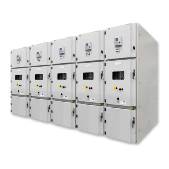
I NT EN DED U S ER S U N IG E AR D IG ITA L UniGear Digital UniGear Digital is a new solution implemented to a traditional UniGear switchgear. It is accomplished by using well-proven components such as current and voltage sensors, Relion ®... -
Page 15: Ethernet Network Verification
ET HER N ET N E T WO R K V ER IF I CAT IO N PR OT E CT IO N R E LAYS Ethernet network verification The Ethernet network interconnects protection relays in a substation. As the GOOSE and Pro- cess bus are used, to make the network functional is essential for most of the tests. -
Page 16: Figure 3: Network Topology Setting And Its Redundancy Mode
PR OT E CT IO N R E LAYS ET HER N ET N E T WO R K V ER IF I CAT IO N Figure 3: Network topology setting and its Redundancy mode Time synchronization setting Check the setting of time synchronization. For Process bus functionality, the IEEE 1588 proto- col must be set up. -
Page 17: Figure 4: Ptp Priority Setting For Master Clock
ET HER N ET N E T WO R K V ER IF I CAT IO N PR OT E CT IO N R E LAYS Figure 4: PTP priority setting for Master clock Other protection relays On the protection relay LHMI go to -> Main Menu/Configuration/Time/Synchronisation –... -
Page 18: Figure 6: Ieee 1588 Master Clock Status
PR OT E CT IO N R E LAYS ET HER N ET N E T WO R K V ER IF I CAT IO N Figure 6: IEEE 1588 master clock status Check the time synchronization status at other protection relays. On the protection relay LHMI go to ->... -
Page 19: Managed Ethernet Switches
Managed Ethernet switches To create a reliable Ethernet network for IEC 61850 communication, a managed Ethernet switch is recommended to be used. The most important settings of ABB’s AFS family Ether- net switches to be observed are highlighted in this section. -
Page 20: Basic Settings
Basic Settings Basic Settings / Port configuration Check Port setting according to the UniGear Digital Engineering Guide. It is recommended to assign a bay to port name according to the project documentation (for example Network Overview diagram). Interconnect the Ethernet cable from the bay (protection relay) to the Ethernet switch port. -
Page 21: Time Settings
ET HER N ET N E T WO R K V ER IF I CAT IO N M A NAG ED E T HER N ET SW I TC HES 3.2.2 Time Settings Check Time setting. It is recommended to set a transparent time with Power profile. The Ethernet switch then only corrects and forwards the PTP messages and cannot become the PTP master. -
Page 22: Switching Settings (Vlan)
M A NAG ED E T HER N ET SW I TC HES ET HER N ET N E T WO R K V ER IF I CAT IO N Figure 13: Transparent clock Port dialogue 3.2.3 Switching Settings (VLAN) The traffic segregation is especially essential for the process bus to reduce data traffic and to let it go only where needed (for example GOOSE, SMV shared between protection relays should not be sent to the control system, SMV should only be sent where required). -
Page 23: Figure 16: Vlan Configuration Dialogue
ET HER N ET N E T WO R K V ER IF I CAT IO N M A NAG ED E T HER N ET SW I TC HES Switching/VLAN Check ports assignment to VLANs in VLAN Configuration dialogue. Setting must match the VLAN ID of GOOSE and SMV messages in PCM600. -
Page 24: Figure 17: Vlan Port Dialogue
M A NAG ED E T HER N ET SW ITC HES ET HER N ET N E T WO R K V ER IF I CAT IO N Figure 17: VLAN Port dialogue SCADA connection There could be GOOSE messages from foreign substations in the SCADA, which may affect interlocks/trips between your panels and therefore must be filtered out. -
Page 25: Prp And Hsr Redundancy Settings
There is no special setting in the Ethernet switch for PRP networks. For more details and a network topology overview, refer to the UniGear Digital Engineering Guide. Check the HSR parameters setting according to the UniGear Digital Engineering Guide. It var- ies based on the used network topology. -
Page 26: Interconnections
I NT ER CO NN E CT IO NS ET HER N ET N E T WO R K V ER IF I CAT IO N Interconnections Check the interconnection of network components (protection relays, managed Ethernet switches …) according to documentation (for example, the Network Overview Diagram). Figure 20: Example of HSR Network overview diagram Figure 21: Interconnection of protection relays into HSR ring 1 VLG 5000 17 C... -
Page 27: Figure 22: Example Of Prp Network Overview Diagram
ET HER N ET N E T WO R K V ER IF I CAT IO N I NT ER CO NN E CT IO NS Figure 22: Example of PRP network overview diagram Figure 23: Interconnection of protection relays into PRP networks 1 VLG 500 0 17 C... -
Page 28: Figure 24: Example Of Plant Structure In Pcm600
I NT ER CO NN E CT IO NS ET HER N ET N E T WO R K V ER IF I CAT IO N Protection relay Check the connection status of protection relays via PCM600. Open the factory delivered pro- ject and select the protection relay for which you want to check the connection. -
Page 29: Figure 25: Goose / Smv Alarm Is Activated On A Configurable Led
ET HER N ET N E T WO R K V ER IF I CAT IO N I NT ER CO NN E CT IO NS Check if No GOOSE / SMV alarm is reported by the receiver protection relays. Figure 25: GOOSE / SMV alarm is activated on a configurable LED Check the Measurements view on the voltage receiver protection relays if voltage values are not in brackets. -
Page 30: Primary Testing
– Licensed software is not required – For pre-testing, secondary tester with sensor support (low voltage output signals) is re- quired – The setting of sensors in the protection relay is described in the UniGear Digital Engineer- ing guide. Recommended primary testing device For primary current and voltage injection you can use existing devices. -
Page 31: Current Sensors
PR IM AR Y T ES T IN G CU R R E N T S EN SO R S Current sensors Primary testing verifies the whole measurement chain including the sensor, cable connec- tions and settings of the protection relay. Each current sensor has unique physical polarity. Therefore, no polarity (physical test) is needed. -
Page 32: Installed Busbars In The Switchgear Panel
CU R R E N T S EN SO R S PR IM AR Y T EST IN G 4.2.2 Installed busbars in the switchgear panel This testing procedure includes the influence of applications such as the circuit breaker or contactor. -
Page 33: Figure 31 Primary Test Setup For Current Sensors When Busbars Are Installed
PR IM AR Y T ES T IN G CU R R E N T S EN SO R S Step 2/5 Move two neighboring circuit breakers into the service position and close them. Default values of overcurrent, earth fault and unbalance protection functions can op- erate the circuit breaker during primary injection. -
Page 34: Figure 32 Measurements View
CU R R E N T S EN SO R S PR IM AR Y T EST IN G Step 5/5 Check the current metering for the phase and measured current in other phases on the pro- tection relay LHMI Measurements view. Current must be zero in phases which are not under the primary injection test. -
Page 35: Non-Installed Busbars In The Switchgear Panel Or Restricted Access To The Busbar Compartment
PR IM AR Y T ES T IN G CU R R E N T S EN SO R S 4.2.3 Non-installed busbars in the switchgear panel or restricted access to the busbar compartment This testing method does not include the influence of application, such as the circuit breaker or contactor. -
Page 36: Figure 35: Test Setup For Current Sensors Testing When Busbars Are Not Installed Or There Is Restricted Access To The Busbar Compartment
CU R R E N T S EN SO R S PR IM AR Y T EST IN G Step 2/6 Remove the circuit breaker out of the switchgear panel. Step 3/6 If there is the high voltage on busbars, secure top shutter with a padlock Step 4/6 In the cable compartment, connect the injection test set to the cable sealing end and the cir- cuit breaker compartment to the branch conductor behind the lower shutter of the same... -
Page 37: Figure 36: Measurements View
PR IM AR Y T ES T IN G CU R R E N T S EN SO R S Step 6/6 Check current metering for the phase and the measured current in other phases on the pro- tection relay LHMI Measurements view. Current must be zero in all phases which are not under the primary injection test. -
Page 38: Non-Installed Busbars In The Switchgear Panel
CU R R E N T S EN SO R S PR IM AR Y T EST IN G 4.2.4 Non-installed busbars in the switchgear panel This testing method includes the influence of application, such as the circuit breaker or con- tactor, which are used to make an electrical circuit between the cable and busbar compart- ments. -
Page 39: Figure 39: Test Setup For Current Sensors When Busbars Are Not Installed
PR IM AR Y T ES T IN G CU R R E N T S EN SO R S Step 2/7 Move the circuit breaker into the service position and close it. Default values of overcurrent, earth fault and unbalance protection functions can op- erate the circuit breaker during primary injection. -
Page 40: Figure 40: Measurements View
CU R R E N T S EN SO R S PR IM AR Y T EST IN G Step 6/7 Check current metering for the phase and measured current in other phases on the protec- tion relay LHMI Measurements view. Current must be zero in phases which are not under the primary injection test. -
Page 41: Voltage Sensors
PR IM AR Y T ES T IN G VO LTAG E SE NSO R S Voltage sensors Primary testing verifies the whole measurement chain including the sensor, cable connec- tions and settings of the protection relay. Physical polarity of the voltage sensor is unique, only one-way installation is possible. -
Page 42: Voltage Sensor Installed In The Cable Compartment
VO LTAG E SE NS O R S PR IM AR Y T EST IN G 4.3.2 Voltage sensor installed in the cable compartment Step 1/7 Verify sensor parameters set in the protection relay with the sensor rating plates placed on the circuit breaker door. -
Page 43: Figure 43: Test Setup For Voltage Sensors Installed In The Cable Compartment
PR IM AR Y T ES T IN G VO LTAG E SE NSO R S Step 4/7 Except the tested phase, connect all other phases together to the grounding bar. Step 5/7 Connect the primary tester to the cable sealing end of the isolated phase and to the ground- ing bar inside the switchgear panel. -
Page 44: Figure 44: Measurements View, Injected Phase 1
VO LTAG E SE NS O R S PR IM AR Y T EST IN G Step 7/7 Check voltage metering for the phase on the protection relay LHMI Measurements view. Figure 44: Measurements view, injected phase 1 Since the protection relay is reporting phase-to-phase voltages, two identical measurements will appear on the display. -
Page 45: Voltage Sensor Installed On Busbars
PR IM AR Y T ES T IN G VO LTAG E SE NSO R S 4.3.3 Voltage sensor installed on busbars Step 1/8 Verify sensor parameters set in the protection relay with the sensor rating plates placed on the circuit breaker door. Figure 45: Example of a voltage sensor label On the protection relay LHMI go to ->... -
Page 46: Figure 47: Test Setup For Voltage Sensors Installed On Busbars
VO LTAG E SE NS O R S PR IM AR Y T EST IN G Step 4/8 Make sure there is no voltage on the busbar. Open the top shutter in the circuit breaker compartment. Step 5/8 Except the tested phase, connect all other phases together to the grounding bar. Step 6/8 Connect the tester to the isolated (measured) phase and grounding bar. -
Page 47: Figure 48: Measurements View, Injected Phase 1
PR IM AR Y T ES T IN G VO LTAG E SE NSO R S Step 8/8 Check voltage metering for the phase on the voltage sender protection relay LHMI Measure- ments view. Figure 48: Measurements view, injected phase 1 Check voltage values for the phase on the voltage receiver protection relays LHMI Measure- ments view. -
Page 48: Apparatus Control Testing
PA N E L I NT ER N A L I NT ER LO C KI NG AP PAR ATU S CO NTR O L T E S TI NG Apparatus control testing It is recommended to test panel internal interlocking and interlocks between panels during maintenance. -
Page 49: Figure 52: Single Line Diagram, The Earthing Switch Shutter Is Open
AP PAR ATU S CO NTR O L T E S TI NG PA N E L I NT ER N A L I NT ER LO C KI NG Step 2/6 Insert the earthing switch crank on the shaft. Check the status on the protection relay LHMI. Figure 52: Single line diagram, the earthing switch shutter is open Step 3/6 Check that the circuit breaker cannot be moved into service position when the earthing... -
Page 50: Figure 54: Single Line Diagram, The Circuit Breaker Is In The Intermediate Position
PA N E L I NT ER N A L I NT ER LO C KI NG AP PAR ATU S CO NTR O L T E S TI NG Step 5/6 Move the circuit breaker truck out of the test position about a half turn of the crank. Check the circuit breaker status on the protection relay LHMI. -
Page 51: Circuit Breaker
AP PAR ATU S CO NTR O L T E S TI NG PA N E L I NT ER N A L I NT ER LO C KI NG 5.1.2 Circuit breaker The circuit breaker can only be closed when the circuit breaker truck is in the test or service position, not in the intermediate position. -
Page 52: Figure 57: Single Line Diagram, The Circuit Breaker Is Open And In The Test Position
PA N E L I NT ER N A L I NT ER LO C KI NG AP PAR ATU S CO NTR O L T E S TI NG Step 2/7 Check the impossibility of inserting the circuit breaker into service when it is closed. Step 3/7 Open the circuit breaker. -
Page 53: Figure 59: Single Line Diagram, The Circuit Breaker Is Closed And In The Service Position
AP PAR ATU S CO NTR O L T E S TI NG PA N E L I NT ER N A L I NT ER LO C KI NG Step 6/7 Move the circuit breaker truck into the service position. Close the circuit breaker. Check the circuit breaker status on the protection relay LHMI. -
Page 54: Earthing Switch
PA N E L I NT ER N A L I NT ER LO C KI NG AP PAR ATU S CO NTR O L T E S TI NG 5.1.3 Earthing switch The earthing switch can only be closed if the circuit breaker is in the test position or the plug is out. -
Page 55: Figure 63: Single Line Diagram, The Earthing Switch Is Closed
AP PAR ATU S CO NTR O L T E S TI NG PA N E L I NT ER N A L I NT ER LO C KI NG Step 3/7 Check that the earthing switch cannot be closed when the circuit breaker is out of the test position. -
Page 56: Interlocks Between Panels
In UniGear Digital, the ordinary inter-panel wiring used for interlocking/tripping is replaced with IEC 61850 GOOSE communication, using the existing Ethernet network inside switch- gear. The realized logic in UniGear Digital over IEC 61850 GOOSE can be as follows: – Busbar earthing switch / Busbar earthing truck –... -
Page 57: Figure 65: Logic Scheme Of The Busbar Earthing Truck Interlock
AP PAR ATU S CO NTR O L T E S TI NG I NT ER LO C K S BE T W EE N PA NE LS The Busbar earthing switch / truck blocking logic operates bi-directionally and therefore re- quire two tests: –... -
Page 58: Figure 67: Single Line Diagram, The Circuit Breaker Is In The Test Position
I NT ER LO C K S BE T W EE N PA NE LS AP PAR ATU S CO NTR O L T E S TI NG Step 1/5 All circuit breakers must be in the test position. Check their status on the protection relay LHMIs on the Single line diagram. -
Page 59: Figure 69: Logic Scheme Of Trucks Interlock By The Busbar Earthing Truck
AP PAR ATU S CO NTR O L T E S TI NG I NT ER LO C K S BE T W EE N PA NE LS Circuit breaker trucks interlock Figure 69: Logic scheme of trucks interlock by the busbar earthing truck Figure 70: Logic scheme of trucks interlock by the busbar earthing switch 1 VLG 500 0 17 C... -
Page 60: Figure 71: Single Line Diagram, The Circuit Breaker Is In The Test Position
I NT ER LO C K S BE T W EE N PA NE LS AP PAR ATU S CO NTR O L T E S TI NG Step 1/4 All circuit breakers in the relative section are in the test position. Check the circuit breakers status via the protection relay LHMIs. -
Page 61: Circuit Breaker Failure Protection (Cbfp)
AP PAR ATU S CO NTR O L T E S TI NG I NT ER LO C K S BE T W EE N PA NE LS 5.2.2 Circuit breaker failure protection (CBFP) The protection relay supervise trip command is processed by the Circuit breaker in the ex- pected “tripping”... -
Page 62: Figure 74: Single Line Diagram Circuit, The Circuit Breaker Is Closed And In The Service Position
I NT ER LO C K S BE T W EE N PA NE LS AP PAR ATU S CO NTR O L T E S TI NG Step 2/10 Close the circuit breaker in the feeder to be tested. Check the circuit breaker status on the protection relay LHMI. -
Page 63: Figure 76: Activating Backup Trip
AP PAR ATU S CO NTR O L T E S TI NG I NT ER LO C K S BE T W EE N PA NE LS Step 6/10 On the protection relay LHMI (tested feeder) go to -> Main Menu/Test/Function tests/ Other protection –... -
Page 64: Figure 78: Entering Test Mode
I NT ER LO C K S BE T W EE N PA NE LS AP PAR ATU S CO NTR O L T E S TI NG Step 7/10 Check the interlocking logic. Clear Lockouts. Step 8/10 On the protection relay LHMI (tested feeder) go to -> Main Menu/Test/IED test –... -
Page 65: Logic Busbar Protection (Lbbp)
AP PAR ATU S CO NTR O L T E S TI NG I NT ER LO C K S BE T W EE N PA NE LS 5.2.3 Logic busbar protection (LBBP) Logic bus bar protection trips selectively the circuit breaker according to the logic scheme. The start signal of the Overcurrent or Earth fault protection is sent from the Outgoing feed- ers to the upstream circuit breaker, such as the Incomer, Generator and Bus tie, to block su- perior Overcurrent or Earth fault protection. -
Page 66: Figure 81: Entering Test Mode
I NT ER LO C K S BE T W EE N PA NE LS AP PAR ATU S CO NTR O L T E S TI NG Step 2/10 On the protection relay LHMI (upstream circuit breaker such as the Incomer, Generator and Bus tie receiving LBBP blocking signal) go to ->... -
Page 67: Figure 83: Activating Blocking Mode
AP PAR ATU S CO NTR O L T E S TI NG I NT ER LO C K S BE T W EE N PA NE LS Step 5/10 On the protection relay LHMI (upstream circuit breaker) go to -> Main Menu/Monitoring/ I/O status/Current protection/PHIPTOC1/Inputs –... -
Page 68: Figure 85: Deactivating Blocking Mode
I NT ER LO C K S BE T W EE N PA NE LS AP PAR ATU S CO NTR O L T E S TI NG Step 7/10 On the protection relay LHMI (upstream circuit breaker) go to -> Main Menu/Monitoring/ I/O status/Current protection/PHIPTOC1/Inputs –... -
Page 69: Overpressure Flaps Inter-Trip
AP PAR ATU S CO NTR O L T E S TI NG I NT ER LO C K S BE T W EE N PA NE LS 5.2.4 Overpressure flaps inter-trip The Overpressure relief flaps are fitted with Ith limiters. These send a trip command to the circuit breaker in case of an electrical Arc inside the switchgear. -
Page 70: Figure 88: Single Line Diagram, The Circuit Breaker Is In The Service Position
I NT ER LO C K S BE T W EE N PA NE LS AP PAR ATU S CO NTR O L T E S TI NG Step 1/6 Move all circuit breaker trucks into the service position in the relative section. Check all the circuit breakers trucks status on the protection relay LHMIs. -
Page 71: Arc Protection Inter-Trip
AP PAR ATU S CO NTR O L T E S TI NG I NT ER LO C K S BE T W EE N PA NE LS 5.2.5 Arc protection inter-trip The switchgear is fitted with lenses detecting flashlight from an electrical Arc in each com- partment. -
Page 72: Figure 92: Entering Test Mode
I NT ER LO C K S BE T W EE N PA NE L S AP PAR ATU S CO NTR O L T E S TI NG Step 2/11 On the protection relay LHMI (upstream circuit breaker such as the Incomer, Generator and Bus tie receiving the ARCSARC trip signal) go to ->... -
Page 73: Figure 94: Activating Operate Signal
AP PAR ATU S CO NTR O L T E S TI NG I NT ER LO C K S BE T W EE N PA NE LS Step 5/11 On the protection relay LHMI (tested feeder) go to-> Main Menu/Test/Function tests/ Other protection –... -
Page 74: Figure 96: Entering Test Mode
I NT ER LO C K S BE T W EE N PA NE LS AP PAR ATU S CO NTR O L T E S TI NG Step 8/11 Repeat step 5 for other stages of Arc protection (represent other compartments of switch- gear) On the protection relay LHMI go to->... -
Page 75: Secondary Testing Of Protection Relays
SE CO NDAR Y T EST ING O F PR OT E CT IO N R E LAYS I NT ER LO C K S BE T W EE N PA NE LS Secondary testing of protection relays In comparison with traditional UniGear switchgear, the overall testing procedure of protec- tion relays has not changed. -
Page 76: Essailec Test Blocks
ES SA I L EC T EST B LO C KS SE CO NDAR Y T ES T ING O F PR OT E CT IO N R E LAYS ESSAILEC test blocks ® ESSAILEC test blocks are used for efficient testing of protection and control relay during regular maintenance. -
Page 77: Figure 101: Essailec ® Trip Test Block - Testing
SE CO NDAR Y T EST ING O F PR OT E CT IO N R E LAYS ESSA I L EC T EST B LO C KS ESSAILEC® Trip or Polarity range test block The test block allows the testing without circuit breaker tripping. Testing procedure Step 1/5 ®... -
Page 78: Figure 103: The Testing (One Phase Testing Setup Is Shown On The Picture)
ES SA I L EC T EST B LO C KS SE CO NDAR Y T ES T ING O F PR OT E CT IO N R E LAYS Step 3/5 Secondary testing Figure 103: The testing (one phase testing setup is shown on the picture) Step 4/5 ®... -
Page 79: Figure 105: Essailec Trip Test Block - Normal Operation
SE CO NDAR Y T EST ING O F PR OT E CT IO N R E LAYS ESSA I L EC T EST B LO C KS Step 5/5 ® Remove the test plug from ESSAILEC Trip test socket and cover it by the lid. ®... -
Page 80: Secondary Test Setups
Test setup for Omicron – 3 phases Low-level outputs of the CMC tester (for example CMC 850; CMC 356; CMC 256plus; CMC 353 / CMC 430) are connected to an adapter CMLIB REF6xx / LLX1 used to connect ABB’s Relion ®... -
Page 81: Figure 107: Linear Current Sensor Instead Of The Rogowski Setting In The Omicron Tester
SE CO NDAR Y T E ST ING O F PR OT E CT IO N R E LAYS SE CO NDAR Y T ES T S ETU P S The maximal low level output from • CM430 + LLX1 is 48 V •... -
Page 82: Figure 108: 1 Phase Test Setup For The Omicron Tester
SE CO NDAR Y T EST S ETU P S SE CO NDAR Y T ES T ING O F PR OT E CT IO N R E LAYS Test Setup for Omicron – 1 phase For high setting of Overcurrent protection, you may need to apply at max. 93.75 Vrms, 50 Hz which represents 50 kA of symmetrical short circuit current on the primary side. -
Page 83: Figure 110: Setting Of High Voltage Analogue Outputs In The Test Universe Program
SE CO NDAR Y T EST ING O F PR OT E CT IO N R E LAYS SE CO NDAR Y T ES T S ETU P S Step 3/3 Simulate high currents on the current sensor input via the front voltage outputs 1, 2. –... -
Page 84: Figure 113: 3 Phases Test Setup For The Megger Tester
SE CO NDAR Y T ES T ING O F PR OT E CT IO N R E LAYS Test Setup for Megger – 3 phases FREJA 546 (Low Level Output Hardware option) is interconnected with a Low-level test adapter. The test adapter provides the interface between ABB’s Relion ® 615/620 series fitted with combined sensor inputs and the tester. -
Page 85: Figure 114: 1 Phase Test Setup For The Megger Tester
SE CO NDAR Y T EST ING O F PR OT E CT IO N R E LAYS SE CO NDAR Y T ES T S ETU P S Test Setup for Megger – 1 phase For high setting of overcurrent protection, you may need to apply at max. 93.75 Vrms, 50 Hz which represent 50 kA symmetrical short circuit current on the primary side. -
Page 86: Figure 116: Setting Of High Voltage Analogue Outputs On The Freja 300 Hmi
SE CO NDAR Y T EST S ETU P S SE CO NDAR Y T ES T ING O F PR OT E CT IO N R E LAYS Step 3/3 Simulate high currents on the current sensor input via the front voltage outputs L1U, L2U. –... -
Page 87: Figure 117: Setting Of High Voltage Analogue Outputs In The Megger Configuration Program
SE CO NDAR Y T EST ING O F PR OT E CT IO N R E LAYS SE CO NDAR Y T ES T S ETU P S Figure 117: Setting of high voltage analogue outputs in the Megger configuration program Figure 118: Setting of high voltage analogue outputs in the Megger configuration program 1 VLG 500 0 17 C... -
Page 88: Figure 119: Measurements View
SE CO NDAR Y T EST S ETU P S SE CO NDAR Y T ES T ING O F PR OT E CT IO N R E LAYS Figure 119: Measurements view 1 VLG 5000 17 C... -
Page 89: Recommended Troubleshooting Tools
SE CO NDAR Y T ES T S ETU PS Recommended Troubleshooting tools ITT SA Explorer Integrated testing tool ITT600 SA Explorer (manufactured by ABB) s designed for easy diag- nosis and troubleshooting of IEC 61850-based substation automation systems and applica- tions. -
Page 90: Figure 121: Home Page For Testing And Commissioning Pages
SE CO NDAR Y T EST S ETU P S R ECO M M E ND ED TR O U B LE S HO OT I NG TO O LS Local HMI of 640 series The LHMI supports the engineer during the relay’s testing, commissioning and troubleshoot- ing activities. -
Page 91: Figure 123: Goose Sending Page
R ECO M M E ND ED TR O U B LE S HO OT I NG TO O LS SE CO NDAR Y T ES T S ETU P S On the page, check the status of the relay's configured GOOSE control blocks GOOSE Sending and the values of the sent data. -
Page 92: Figure 125: Smv Sending Page
SE CO NDAR Y T EST S ETU P S R ECO M M E ND ED TR O U B LE S HO OT I NG TO O LS On the page, check the status of the relay's configured SMV control blocks and SMV Sending the values of the sent IEC 61850-9-2 sampled value data. -
Page 93: Figure 126: Example Of Captured Packets By Wireshark
R ECO M M E ND ED TR O U B LE S HO OT I NG TO O LS SE CO NDAR Y T ES T S ETU P S Wireshark Network analyzer Wireshark is an open source network packet analyzer. A network packet analyzer captures network packets and displays that packet data as detailed as possible. - Page 94 620 series protection and control relays ® 640 series Relion 640 series protection and control relays Application Configuration Tool AFS Family ABB FOX Switch family for utility applications Busbar Circuit Breaker CBFP Circuit Breaker Failure protection Current Transformer Ethernet A standard for connecting a family of frame-based...
- Page 95 R ECO M M E ND ED TR O U B LE S HO OT I NG TO O LS SE CO NDAR Y T ES T S ETU P S Manufacturing Message Specification Medium voltage Personal computer PCM600 Protection and control relay Manager Parallel Redundancy Protocol PTPv2 Precision Time Protocol Version 2...
- Page 97 Revision History Rev. Page Change Description Date / Initial Initial release 2016-03-15 ESSAILEC ® test blocks for the secondary testing without opening a 2017-03-27 low voltage compartment door Recommended Troubleshooting tools Recommended 3 phase test set up extended about FREJA 546 with 2019-12-19 low level output hardware option and about Omicron CMC 430 with low level output accessories LLX1...
- Page 98 — Visit us www.abb.com/mediumvoltage...
Need help?
Do you have a question about the UniGear Digital and is the answer not in the manual?
Questions and answers