Sign In
Upload
Manuals
Brands
ABB Manuals
Switch
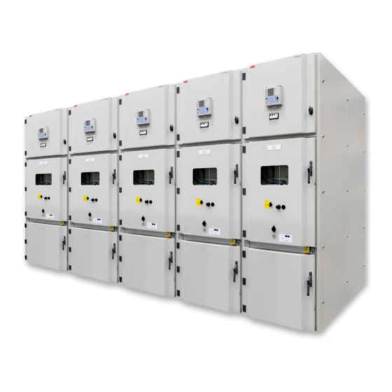
UniGear Digital
ABB UniGear Digital Manuals
Manuals and User Guides for ABB UniGear Digital. We have
2
ABB UniGear Digital manuals available for free PDF download: Engineering Manual, Commissioning And Testing Manual
ABB UniGear Digital Engineering Manual (112 pages)
Brand:
ABB
| Category:
Switch
| Size: 7.49 MB
Table of Contents
Table of Contents
5
Introduction
13
This Manual
13
Intended Users
13
Unigear Digital
14
Figure 1: Unigear Digital and Its Key Components
14
Sensors
15
Table 1: Sensor Product Portfolio for Unigear Digital
15
Current Sensors
16
Figure 2: Current Sensor KECA 80 C104 / KECA 80 C165
16
Figure 3: Current Sensor KECA 80 C184 / KECA 80 C216
17
Figure 4: Current Sensor KECA 250 B1
18
Voltage Sensors
19
Figure 5: Voltage Sensor KEVA 17.5 B20
19
Figure 6: Voltage Sensor KEVA 24 B20
20
Figure 7: Coupler Adapter AR5 Utilized with Relion
21
Figure 8: Connector Pins Assignment of a Current Sensor Plug
22
Figure 9: Connector Pins Assignment of a Voltage Sensor Plug
22
Protection Relays
23
Table 2: Protection Relay Key Functionality Overview for Unigear Digital
23
Figure 10: Functionality Overview of REF615 Standard Configuration G
24
Figure 11: Functionality Overview of REF615 Standard Configuration L
25
Figure 12: Functionality Overview of REM615 Standard Configuration D
26
Figure 13: Functionality Overview of RED615 Standard Configuration E
27
Figure 14: Functionality Overview of REF620 Standard Configuration B
28
Figure 15: Functionality Overview of REM620 Standard Configuration B
29
Figure 16: Protection and Control REX640
30
Figure 17: Overview of RIO600 Connection
31
Figure 18: RIO600 Communicating Analog Signals for the Panel Meters
31
Figure 19: ESSAILEC ® RJ45 Test Block
32
Figure 20: Low Voltage Compartment Door with ESSAILEC ® RJ45 Test Blocks
32
Figure 21: the Testing (Only One Phase Is Shown)
32
Iec 61850
33
Figure 22: Switchgear with Sensor Measurement
33
Figure 23: Switchgear with Sensor Measurement and Process Bus Application of Voltage Sharing and Synchrocheck
34
Switchgear Type Overview
35
Figure 24: Unigear ZS1 Digital (17.5 Kv, 4 000 A, 50 Ka)
35
Table 3: Overview of Unigear Digital in Unigear Switchgear Family
35
Figure 25: Unigear ZS1 Digital (24 Kv, 3 150 A, 31.5 Ka)
36
Figure 26: Unigear 550 Digital (12 Kv, 1 250 A, 31.5 Ka)
36
Figure 27: Unigear 500R Digital (17.5 Kv, 2 000 A, 31.5 Ka)
37
Figure 28: Unigear MCC Digital (12 Kv, 400 A, 50 Ka)
37
Engineering
38
Sensors
38
Current Sensors
38
Figure 29: Example of a Current Sensor Label
38
Figure 30: Example of Setting the Correction Factors for Current Sensor in PCM600
38
Figure 31: Single Line Diagram
39
Figure 32: Example of Setting Values for Current Sensor in PCM600
40
Figure 33: Example of Parameter Setting for PHIPTOC1 Start Value in PCM600
40
Figure 34: Current Sensor with Unique Physical Polarity
41
Table 4: Maximum Current Start and Protection Setting Values
41
Figure 35: Polarity Setting for Current Sensors in Incoming Feeder
42
Figure 36: Example of Polarity Setting for Current Sensor in PCM600
42
Voltage Sensors
43
Figure 37: Example of a Voltage Sensor Label
43
Figure 38: Example of Setting the Correction Factors for Voltage Sensor in PCM600
43
Figure 39: Single Line Diagram
44
Figure 40: Example of Setting Values for Voltage Sensor in PCM600
44
Documentation
45
Figure 41: Example of a Network Overview Diagram
45
Figure 42: Example of a Logic Diagram for Interconnection between Panels
45
Figure 43: Example of a Sampled Measured Value Diagram
46
Station Bus (GOOSE)
47
Figure 44: Creating a New GOOSE Data Set and Its Entries
48
Figure 45: GOOSE Control Block Properties
48
Figure 46: GOOSE Control Block Editor (1- Receiver #1, 2- Receiver #2, 3 - Sender)
50
Figure 47: Selecting Show IED Capabilities Tab
50
Figure 48: Editing 615 Series Capabilities
51
Figure 49: Creating a New GOOSE Data Set and Its Entries
51
Figure 50: Naming a GOOSE Control Block
52
Figure 51: GCB Client
52
Figure 52: Adding a GOOSERCV Function Block in the Application Configuration Tool
53
Figure 53: Creating GOOSERCV Block Connection to a New Variable
53
Figure 54: Signal Matrix
53
Process Bus (SMV)
54
Figure 55: Example of Process Bus Application of Voltage Sharing and Synchro-Check
54
Figure 56: Example of Process Bus Application of Voltage Sharing Redundancy and Synchro Check
54
Figure 57: Adding a SMSENDER Block in the Application Configuration Tool
55
Figure 58: Adding a ULTVTR1 Block in the Application Configuration Tool
55
Figure 59: Time Parameter Setting Dialog in PCM600
56
Figure 60: Configuring the SMV Senders and Receivers
57
Figure 61: Changing the Sampled Measured Value Control Block Attributes
58
Figure 62: Selecting Show IED Capabilities Tab
59
Figure 63: Editing 615 Series Capabilities
60
Figure 64: Sampled Value Control Block
60
Figure 65: Connecting the SMV Senders and Receivers
60
Figure 66: Receiving All Phase Voltages and Residual Voltage Using SMV
61
Figure 67: Receiving Line Voltage for Synchrocheck Functionality Using SMV
61
Figure 68: Application Configuration Tool Logic Examples for the SMV Fail Save Operation
62
Figure 69: SMV Max Delay Setting in PCM600
63
Table 5: Topology-Dependent SMV Max Delay Setting
63
Ethernet
64
Requirements
64
Technology
65
Figure 70: FTP Patch Cable Terminated with RJ-45 Connectors
65
Figure 71: Fiber Optic Patch Cable Terminated with LC Connectors
65
Figure 72: LC Connectors
66
Figure 73: Communication Module with Single Ethernet Connector
66
Figure 74: Communication Modules with Multiple Ethernet Connectors
67
Table 6: Recommended Managed Ethernet Switches Overview for Unigear Digital
68
Figure 75: Example of Managed Ethernet Switches from AFS Family
69
Figure 76: 1 - Fast Ethernet Fiber Optic SFP Module, 2 - Gigabit Ethernet Fiber Optic SFP Module
69
Figure 77: Installed SFP Module in Managed Ethernet Switch AFS677
69
Figure 78: Example of Satellite Controlled Clock from Tekron with Optional Accessories
70
Figure 79: Example of Satellite Controlled Clock from Meinberg
71
Figure 80: Low Voltage Compartment of Unigear Panel
71
Topologies
72
Figure 81: RSTP Ring Redundant Structure
72
Figure 82: MRP / E-MRP Ring Redundant Structure
73
Figure 83: Single Network Using RSTP / E-MRP
73
Figure 84: PRP Networks Using RSTP / E-MRP
74
Figure 85: HSR Network
75
Figure 86: HSR Network with Redboxes
75
Figure 87: Combined PRP and HSR Networks
76
Table 7: Comparison of Network Topologies
77
Ethernet Traffic Estimation
78
Naming Convention to Identify Protection Relays
79
IP Address Allocation
79
Time Synchronization
80
Figure 88: Example of an Allocation of Device IP Addresses
80
Figure 89: Example of IEEE 1588-Time Synchronization Via the Ethernet Network
80
Table 8: C37.238 Power Profile Key Parameters
81
Figure 90: IEEE 1588 Time Synchronization Scheme for HSR-PRP Networks
82
Figure 91: IEEE 1588 Time Synchronization Scheme for PRP Networks
82
Traffic Segregation
83
Figure 92: Example of Traffic Segregation Via Building Virtual Lans
83
Figure 93: Virtual Lans Allocation in PRP-RSTP Networks
83
Figure 94: Virtual Lans Allocation in HSR-PRP Networks
84
Protection Relays
85
Figure 95: Communication Parameter Setting Dialog
85
Figure 96: Adding RCHLCCH and SCHLCCH Blocks in the Application Configuration Tool
86
Figure 97: Status of Ethernet Rear Port Displayed Via ITT SA Explorer (on Top and on Bottom)
87
Managed Ethernet Switches
88
Figure 98: AFS Switch Screen
88
Figure 99: Login Window
88
Figure 100: Network Parameters Dialog
89
Figure 101: Port Configuration Dialog
89
Figure 102: Load/Save Dialog
90
Figure 103: PTP Global Dialog
91
Figure 104: PTP Version 2 (Transparent Clock) Global Dialog
91
Figure 105: PTP Version 2 (Transparent Clock) Port Dialog
92
Figure 106: Switching Global Dialog in Afs67X (on Top) and Afs66X (on Bottom)
93
Figure 107: VLAN Global Dialog in Afs67X
94
Figure 108: VLAN Static Dialog
94
Figure 109: VLAN Port Dialog
95
Figure 110: Spanning Tree Global Dialog
96
Figure 111: Spanning Tree Ports Dialog
96
Figure 112: E-MRP Ring Redundancy Dialog
97
Figure 113: Example of AFS660 Front View
98
Figure 114: Switching Global Dialog
98
Figure 115: PRP Configuration Dialog
99
Figure 116: HSR Configuration Dialog
100
Figure 117 : IEC61850-MMS Configuration Dialog
100
Satellite Controlled Clock
101
Figure 118: Tekron Clock Configuration Tool
101
Figure 119: Basic Setting Dialog
102
Figure 120: PTP Setting Dialog
102
Figure 121: Port Configuration Dialog
103
Figure 122: PTP Setting Dialog
103
Figure 123: PTP Global Settings Dialog
104
Figure 124: PTP Network Settings Dialog
105
Advertisement
ABB UniGear Digital Commissioning And Testing Manual (98 pages)
Brand:
ABB
| Category:
Home Automation
| Size: 4.27 MB
Table of Contents
Table of Contents
5
1 Introduction
13
This Manual
13
Intended Users
13
2 Unigear Digital
14
Figure 1: Unigear Digital and Its Key Components
14
3 Ethernet Network Verification
15
Protection Relays
15
Figure 2: IP Address Setting for Rear Port(S)
15
Figure 3: Network Topology Setting and Its Redundancy Mode
16
Figure 4: PTP Priority Setting for Master Clock
17
Figure 5: PTP Priority Setting for Slave Clock
17
Figure 6: IEEE 1588 Master Clock Status
18
Figure 7: IEEE 1588 Slave Clock Status
18
Managed Ethernet Switches
19
Figure 8: Properties Dialogue of Discovered Ethernet Switch by AFS Finder
19
Figure 9: Login Window
19
Basic Settings
20
Figure 10: Port Configuration Dialogue
20
Figure 11: PTP Global Dialogue
21
Figure 12: PTP Transparent Clock Global Dialogue
21
Time Settings
21
Figure 13: Transparent Clock Port Dialogue
22
Figure 14: Switching VLAN Global Dialogue in Afs67X
22
Figure 15: Switching Global Dialogue in Afs66X
22
Switching Settings (VLAN)
22
Figure 16: VLAN Configuration Dialogue
23
Figure 17: VLAN Port Dialogue
24
Figure 18: VLAN Configuration Dialogue (Port 6 Is Connected to SCADA)
24
Figure 19: HSR Configuration
25
PRP and HSR Redundancy Settings
25
Interconnections
26
Figure 20: Example of HSR Network Overview Diagram
26
Figure 21: Interconnection of Protection Relays into HSR Ring
26
Figure 22: Example of PRP Network Overview Diagram
27
Figure 23: Interconnection of Protection Relays into PRP Networks
27
Figure 24: Example of Plant Structure in PCM600
28
Figure 25: GOOSE / SMV Alarm Is Activated on a Configurable LED
29
Figure 26: Measurements View, Voltage Receiver Protection Relay Is Not Synchronized with the Master Clock
29
Figure 27: Measurements View, Voltage Receiver Protection Relay Is Synchronized with the Master Clock
29
4 Primary Testing
30
Recommended Primary Testing Device
30
Figure 28: Primary Test System CPC 100 from Omicron
30
Current Sensors
31
Supervision
31
Table 1: Current Metering Accuracy
31
Table 2: Zero-Clamping Limits
31
Installed Busbars in the Switchgear Panel
32
Figure 29: Example of a Current Sensor Label
32
Figure 30: Current Sensor Parameters
32
Figure 31 Primary Test Setup for Current Sensors When Busbars Are Installed
33
Figure 32 Measurements View
34
Non-Installed Busbars in the Switchgear Panel or Restricted Access to the Busbar Compartment
35
Figure 33: Example of a Current Sensor Label
35
Figure 34: Current Sensor Parameters
35
Figure 35: Test Setup for Current Sensors Testing When Busbars Are Not Installed or There Is Restricted Access to the Busbar Compartment
36
Figure 36: Measurements View
37
Non-Installed Busbars in the Switchgear Panel
38
Figure 37: Example of a Current Sensor Label
38
Figure 38: Current Sensor Parameters
38
Figure 39: Test Setup for Current Sensors When Busbars Are Not Installed
39
Figure 40: Measurements View
40
Voltage Sensors
41
Supervision
41
Table 3: Voltage Metering Accuracy
41
Table 4: Zero-Clamping Limits
41
Voltage Sensor Installed in the Cable Compartment
42
Figure 41: Example of a Voltage Sensor Label
42
Figure 42: Voltage Sensor Parameters
42
Figure 43: Test Setup for Voltage Sensors Installed in the Cable Compartment
43
Figure 44: Measurements View, Injected Phase 1
44
Voltage Sensor Installed on Busbars
45
Figure 45: Example of a Voltage Sensor Label
45
Figure 46: Voltage Sensor Parameters
45
Figure 47: Test Setup for Voltage Sensors Installed on Busbars
46
Figure 48: Measurements View, Injected Phase 1
47
Figure 49: Measurements View, Injected Phase 1
47
5 Apparatus Control Testing
48
Panel Internal Interlocking
48
Circuit Breaker Truck (Disconnector)
48
Figure 50: Blocking Conditions of the Circuit Breaker Truck in PCM600
48
Figure 51: Single Line Diagram, the Circuit Breaker Is Open and in the Test Position
48
Figure 52: Single Line Diagram, the Earthing Switch Shutter Is Open
49
Figure 53: Single Line Diagram, the Earthing Switch Shutter Is Closed
49
Figure 54: Single Line Diagram, the Circuit Breaker Is in the Intermediate Position
50
Circuit Breaker
51
Figure 55: Blocking Conditions of the Circuit Breaker in PCM600
51
Figure 56: Single Line Diagram, the Circuit Breaker Is Closed and in the Test Position
51
Figure 57: Single Line Diagram, the Circuit Breaker Is Open and in the Test Position
52
Figure 58: Single Line Diagram, the Circuit Breaker Is in the Intermediate Position
52
Figure 59: Single Line Diagram, the Circuit Breaker Is Closed and in the Service Position
53
Earthing Switch
54
Figure 60: Blocking Conditions of the Earthing Switch in PCM600
54
Figure 61: Single Line Diagram, the Circuit Breaker Is Open and in the Test Position
54
Figure 62: Single Line Diagram, the Circuit Breaker Is in the Intermediate Position
54
Figure 63: Single Line Diagram, the Earthing Switch Is Closed
55
Interlocks between Panels
56
Busbar Earthing Switch / Truck
56
Figure 64: Example of Process Bus Application in Medium Voltage Switchgear
56
Figure 65: Logic Scheme of the Busbar Earthing Truck Interlock
57
Figure 66: Logic Scheme of the Busbar Earthing Switch Interlock
57
Figure 67: Single Line Diagram, the Circuit Breaker Is in the Test Position
58
Figure 68: Single Line Diagram, the Circuit Breaker Is in the Intermediate Position
58
Figure 69: Logic Scheme of Trucks Interlock by the Busbar Earthing Truck
59
Figure 70: Logic Scheme of Trucks Interlock by the Busbar Earthing Switch
59
Figure 71: Single Line Diagram, the Circuit Breaker Is in the Test Position
60
Circuit Breaker Failure Protection (CBFP)
61
Figure 72: Logic Scheme of CBFP
61
Figure 73: Single Line Diagram, the Circuit Breaker in the Service Position
61
Figure 74: Single Line Diagram Circuit, the Circuit Breaker Is Closed and in the Service Position
62
Figure 75: Entering Test Mode
62
Figure 76: Activating Backup Trip
63
Figure 77: Deactivating Backup Trip
63
Figure 78: Entering Test Mode
64
Logic Busbar Protection (LBBP)
65
Figure 79: Logic Scheme of the Logic Busbar Protection
65
Figure 80: Single Line Diagram, the Circuit Breaker Is in the Service Position
65
Figure 81: Entering Test Mode
66
Figure 82: Activating START Signal
66
Figure 83: Activating Blocking Mode
67
Figure 84: Deactivating START Signal
67
Figure 85: Deactivating Blocking Mode
68
Figure 86: Entering Test Mode
68
Overpressure Flaps Inter-Trip
69
Figure 87: Logic Scheme of Ith Limiters Trip
69
Table 5: Inter-Tripping Rules for Ith Limiters
69
Figure 88: Single Line Diagram, the Circuit Breaker Is in the Service Position
70
Figure 89: Single Line Diagram, the Circuit Breaker Is Closed and in the Service Position
70
Arc Protection Inter-Trip
71
Figure 90: Logic Scheme of ARC Trip
71
Figure 91: Single Line Diagram, the Circuit Breaker Is in the Service Position
71
Figure 92: Entering Test Mode
72
Figure 93: Single Line Diagram, the Circuit Breaker Is Closed and in the Service Position
72
Figure 94: Activating OPERATE Signal
73
Figure 95: Deactivating OPERATE Signal
73
Figure 96: Entering Test Mode
74
6 Secondary Testing of Protection Relays
75
Figure 97: Changing Correction Factors for Amplitude
75
Figure 98: Changing Correction Factors for Angle
75
ESSAILEC Test Blocks
76
Figure 99: ESSAILEC RJ45 Test Block (the Plug, the Lid and the Socket)
76
Figure 101: ESSAILEC ® Trip Test Block - Testing
77
Figure 102: ESSAILEC ® RJ45 Test Block - Testing
77
Figure 103: the Testing (One Phase Testing Setup Is Shown on the Picture)
78
Figure 104: ESSAILEC RJ45 Test Block - Normal Operation
78
Figure 105: ESSAILEC Trip Test Block - Normal Operation
79
Figure 106: 3 Phases Test Setup for the Omicron Testers
80
Secondary Test Setups
80
Figure 107: Linear Current Sensor Instead of the Rogowski Setting in the Omicron Tester
81
Figure 108: 1 Phase Test Setup for the Omicron Tester
82
Figure 109: Connecting Cable with RJ45 Connector and Banana Contacts (It Is Available on Client Request)
82
Figure 110: Setting of High Voltage Analogue Outputs in the Test Universe Program
83
Figure 111: Phasor Diagram on the Protection Relay's Webhmi
83
Figure 112: Measurements View
83
Figure 113: 3 Phases Test Setup for the Megger Tester
84
Figure 114: 1 Phase Test Setup for the Megger Tester
85
Figure 115: Connecting Cable with RJ45 Connector and Banana Contacts (It Is Available on Client Request)
85
Figure 116: Setting of High Voltage Analogue Outputs on the Freja 300 HMI
86
Figure 117: Setting of High Voltage Analogue Outputs in the Megger Configuration Program
87
Figure 118: Setting of High Voltage Analogue Outputs in the Megger Configuration Program
87
Figure 119: Measurements View
88
7 Recommended Troubleshooting Tools
89
Figure 120: ITT600 - Explore SV - Two Selected Streams and the Polar Diagrams Are Shown
89
Figure 121: Home Page for Testing and Commissioning Pages
90
Figure 122: GOOSE Receiving Page
90
Figure 123: GOOSE Sending Page
91
Figure 124: SMV Receiving Page
91
Figure 125: SMV Sending Page
92
Figure 126: Example of Captured Packets by Wireshark
93
Figure 127: Gridex IEC 61850 Test Tool
93
Advertisement
Related Products
ABB UniGear Series
ABB UniSec SDS
ABB UniSec SFC
ABB UniSec SDM
ABB UniSec SFS
ABB UniSec SBC-W
ABB UniSec SBS-W
ABB UniSec SBR
ABB UniSec DRC
ABB UniSec WBS
ABB Categories
Industrial Equipment
Controller
Measuring Instruments
Battery Charger
DC Drives
More ABB Manuals
Login
Sign In
OR
Sign in with Facebook
Sign in with Google
Upload manual
Upload from disk
Upload from URL