
Related Manuals for Hawk Centurion CGR Series


Summary of Contents for Hawk Centurion CGR Series
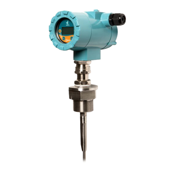
- Page 1 A Higher Level of Performance User Manual Centurion Guided Radar CGR Modbus Interface Series For more information, please visit > www.hawkmeasure.com...
-
Page 2: Table Of Contents
Table of Contents Centurion Guided Radar Contents Overview Displayed Information Principle of Operation Displayed Measurements Function Displayed Diagnostics Features Software Parameters Primary Areas of Application Setup Menu Wiring & Dimensions Digitize Function / Measured Range Reference Wiring Terminal Compartment Dimensions Housing + Barrier Gland Digitize Function Dimensions - Reference Measured Range Reference... -
Page 3: Overview
Function Primary Areas of Application The HAWK range of Guided Radar products are ideal • Chemicals • Food & Beverages for the measurement of liquids, sludge, powders •... -
Page 4: Wiring & Dimensions
Wiring & Dimensions Centurion Guided Radar Blue White (D1) (D0) HAWKLINK-USB Wiring Terminal Compartment Dimensions - Reference PC with GoshawkII (v6.0.67 or later) PE (Protective Earth) screw Housing Barrier Gland / High Temp extension with 110mm (4.33”) 160mm ( Barrier Gland / End position with Barrier Gland Threaded Connection... -
Page 5: Dimensions
Dimensions Centurion Guided Radar Dimensions - Probe Variants A04 / A06 / A08 / J04 / J06 / J08 B04 / B06 / B08 / K04 / K06 / K08 Threaded Welded Flange Threaded Welded Flange Probe / Cable Dimensions Probe BSP or NPT (Tightening Torque = 20Nm) -
Page 6: Cable Weight Tank Fastening Kit
Dimensions Centurion Guided Radar Cable Weight Tank Fastening Kit The tank fastening kit (CGR-A0X-WL-SS) includes 2 eye bolts and 1 adjustable rigging lock. Rigging Lock Dimensions T (thread) 14mm (0.55") 12mm (0.47") 25mm (0.98") 252mm (9.9") 150mm (5.9") Recommended Working Load 983kg (1.05 ton) Total Deformation Load 3750kg (4.13 ton) -
Page 7: Detached Probe Assembly
(refer Table) Rope Weight Apply Loctite 263 or Equivalent onto Set Screws in 3 places. See Detail View Note: Only Probes supplied by HAWK can be fitted Flexible Rigid in situ. Mounting of any other probe voids Hazardous Probe Probe... -
Page 8: Installation Guide
Installation Guide Centurion Guided Radar Mounting - Instruction for Rotating the Housing There are specific rotation points which should be used while mounting the unit into place. The Housing Compartment should never be used to rotate the device during mounting. For rotating the housing after installation, see 'Rotating the Enclosure' section. -
Page 9: Placement Requirements
Installation Guide Centurion Guided Radar Placement Requirements mount near infeed mount over or adjacent to any obstacles Nozzle / Socket Mounting Nozzle / Socket should not protrude into vessel... -
Page 10: Stand Pipe / Flanged Mounting
Installation Guide Centurion Guided Radar Stand Pipe / Flanged Mounting 1. Stand pipes protruding into vessel may cause signal interference. Digitisation and / or Blanking Distance must be adjusted to avoid measurement issues 2. Long / narrow stand pipes may cause signal interference. -
Page 11: Mounting - Conductive Vessel
Unit performance is most optimized when there is a ground reference between the mounting (metal flange or thread) and the vessel. Metallic or metal reinforced vessels are ideal. ProComSol HART modem or HART Hawk supplied M195 USB modem HART modem Mounting - Non Conductive Vessel... -
Page 12: Securing The End Of The Probe
Installation Guide Centurion Guided Radar Securing The End of The Probe • Securing the end of rigid probes is not required unless there is risk of excessive lateral forces. • Securing flexible cable weight via M10 thread on base of weight is recommended to prevent movement. xible Rigid Flexible... -
Page 13: Hardware Adjustment
Hardware Adjustment Centurion Guided Radar Adjusting Probe Length Rigid Probes Cut rigid probes to appropriate length. After adjustment, you must change the 'ProbeLength' Parameter in (password 222) 'Advanced' menu to represent the new length Flexible Probes (a) Mark the point at which the flexible cable enters the cable weight. (b) Release the cable weight grub screws with hex key. -
Page 14: Rotating Non Ex D Rated Enclosures (Page 1 Of 2)
Hardware Adjustment Centurion Guided Radar Rotating non Ex d Rated Enclosures (page 1 of 2) The gland which couples the sensing probe to the enclosure provides a critical sealing function for the enclosure. Internal wires are passed through this gland and the high integrity seal. This gland incorporates a Union Joint which is designed to rotate. -
Page 15: Rotating Non Ex D Rated Enclosures (Page 2 Of 2)
Hardware Adjustment Centurion Guided Radar Rotating non Ex d Rated Enclosures (page 2 of 2) 36mm This is a Sealed Threaded Joint. It must NOT Plane of Rotation be loosened or broken. When Installing the CGR unit, use spanner or wrench ONLY at Process Fitting as indicated. -
Page 16: Forces On The Probe
Forces On The Probe Centurion Guided Radar Forces On The Probe Tensile forces are heavily dependent on the viscosity and abrasive characteristics of the product in the vessel. Ensure tensile loading is appropriate for the selected cable as well as the silo cover and mounting structure. In critical cases it is better to select the larger flexible cable (8mm). -
Page 17: Powering The Unit For The First Time
C. Check the wiring is correct and all connections are secure. D. Apply power to the unit. When power is applied the unit will start its normal load sequence. The following messages will cycle on the display. Hawk CGR Series Serial Number Software Revision... -
Page 18: Displayed Information
Displayed Information Centurion Guided Radar High Level Level 1 Level 2 Displayed Measurements Low Level Measured Span Reference Distance - measured from base of thread or bottom of flange to material level Level - measured from Low level to material level % Level - proportional percentage of measured level based on Low and High level setting High Level... -
Page 19: Software Parameters
Device ID (For HART, FF, PA) Echo s1.5 LEVEL Software Parameters 2.525 Tag xxxxxxx Centurion Guided Radar LEVEL Sensitivity value 2.525 Instrument Tag ID Setup Menu Main Menu Main Menu Setup Advanced Setup Display Mode Comms Advanced Display Unit Tracking Autoset Hi Level Sensitivity... -
Page 20: Digitize Function / Measured Range Reference
Measurable Span (blanking to top of cable weight or end of 24VDC rigid probe). 250ohm High level must be = to or > than Blanking ProComSol HART modem or HART Hawk supplied M195 USB modem Minimum Range (Blanking) Maximum Range HART modem Probe Probe... -
Page 21: Software Parameters
Instrument Tag ID Software Parameters Centurion Guided Radar Main Menu Main Menu Setup Advanced Setup Display Mode Comms Advanced Display Unit Tracking Autoset Hi Level Sensitivity Digitize Low Level Advanced Menu Cal Mount Damping Main Menu Echo Size Fail Mode Analogue Main Menu Factry Reset... -
Page 22: Interface Mode
Interface Mode Centurion Guided Radar Interface Mode Setup The Interface mode is designed to measure applications with low to high dielectric constant layers. The transmited signal relfects off the Upper Layer and continues through the Interface and reflects from the Lower Layer. -
Page 23: Setup Procedure
Setup Procedure Centurion Guided Radar Commissioning For commissioning via PC and GosHawk, see dedicated CGR GosHawk Manual. Parameter Instruction 1. Set Interface Mode If the application is NOT an Interface application, disable Interface mode. High and Low level distances can be programmed manually or you can run 2. -
Page 24: Modbus
Modbus Centurion Guided Radar Registers Address Variable / Description Conversion to Feet Measurement Reference Primary Variable (Level 2 Level in mm) Div. by 304.7851 Secondary Variable (Level 1 Level in mm) Div. by 304.7851 Tertiary Variable (Interface Height in mm) Div. -
Page 25: Software Flow Chart
Software Flow Chart Centurion Guided Radar Diagnostics Autoset __mA Set Lo Level Normal Recover Failed Level 1 Set Hi Level Level 2 Volume Setup Level Display Mode %Level Distance CenMeter Metres Display Unit Feet Inches High Level Low Level Tracking Slow... - Page 26 Software Flow Chart < 80 Centurion Guided Radar > 80 Digitize Confirm? DigitizeDist Yes / No Damping 3.80mA > 20.20mA Last Known FailSafe 20mA FailTime > 21.50mA Advanced DeviceID Comms Baud Rate Blanking Sensitivity Offset Dist Dist Calibrt...
- Page 27 Blanking ProbeFault Enable Software Flow Chart Centurion Guided Radar Interface Disable Sensitivity Enable DK Comp Offset Dist IFace Width Dist Calibrt IFace Size Factry Reset Calibrt Dist Confirm Sel? Yes / No ProbeLength EntrPassword Probe Length Language English Disable Device Info Disable ProbeFault Enable...
-
Page 28: Troubleshooting
Troubleshooting Centurion Guided Radar Troubleshooting Problem Check Check incoming power on loop is to specification. Display is blank Check incoming power on loop is continuous. Unit continually re-starts Bench test with new 24V supply. Run Digitize routine. If routine has already been run, Lower Dielectric selection or increase Sensitivity parameter. - Page 29 The probe is too long See 'Hardware Adjustment / Modifying Probe Length' Adjusting / You will require a HAWKLINK-USB PC connector and HAWK GosHawkII software. commissioning the unit See CGR GosHawk user manual' for further information. without removing the lid If Digitize displays a closer distance than the Upper Material level / end of probe enter the distance to the correct Upper Material Level.
-
Page 30: Part Numbering
Part Numbering Centurion Guided Radar Centurion Guided Radar System Model CGR4 4 wire Centurion Guided Radar, 14-28VDC Communication Modbus with Interface Measurement Housing Aluminum, Epoxy Painted 316L Stainless Steel Gland Entry 1/2” NPT Cable gland entry 3/4” NPT Cable gland entry M20 x 1.5 Cable gland entry M25 x 1.5 Cable gland entry Probe Type... -
Page 31: Probe Combination Table
Part Numbering Centurion Guided Radar Probe Combination Table Probe / Mounting Combination Table Each line represents valid part combinations Probe Code Variant / Materials Mounting Flange Sizes Max. Length Min. Size Max size A04 / J04 TN07, TB07, FXXX 1”, DN25, 25mm 1-1/2”, DN40, 40mm 1850cm A06 / J06... -
Page 32: Flange Table
Flange Table Centurion Guided Radar Mounting Flanges Threaded Flanges Welded Flanges Model Model Flange Size Flange Size 1” or DN25 or 25mm 1” or DN25 or 25mm 1 1/2” or DN40 or 40mm 1 1/2” or DN40 or 40mm 2” or DN50 or 50mm 2”... -
Page 33: Specifications
Specifications Centurion Guided Radar Electronics Power Memory • 24VDC (14 to 28VDC) • Non-Volatile (No backup battery required) >10 years data retention Power Consumption Operating Temperature (Electronics) • <500mW @ 24VDC • -40ºC to +80ºC (-40 to +176ºF) Communications Display •... - Page 34 Specifications Centurion Guided Radar Probe 110mm (4.33”) 160mm (6.3”) Probe Size / Wetted Materials Process Pressure* • -1 to 100 BAR • 4mm SS316L rod • 4mm DIN3055 (7x7 strand) SS316L flexible cable Process Temperature • 6mm SS316L rod • -40ºC to +80ºC (-40 to +176ºF) •...
- Page 35 Centurion Guided Radar Level measurement of liquids, sludge, powders and granules to a distance of 18.5 metres.
-
Page 36: Ordering Instructions
Assemble part number taking note of the valid combinations and exclusions for the full system. In the Mounting part code enter 4 character Welded flange code from the table. All Welded flanges have F as the first character. For example: CGR4W13B08SF4A1B11XX200 Hawk Measurement Systems Hawk Measurement (Head Office) 90 Glenn Street...
Need help?
Do you have a question about the Centurion CGR Series and is the answer not in the manual?
Questions and answers