Nibe SMO S40 Installer Manual
Hide thumbs
Also See for SMO S40:
- Installer manual (80 pages) ,
- User manual (20 pages) ,
- Technical information (16 pages)
Table of Contents
Advertisement
Quick Links
Advertisement
Table of Contents

Related Manuals for Nibe SMO S40


Summary of Contents for Nibe SMO S40
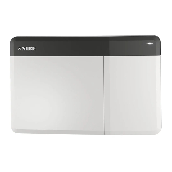
- Page 1 IHB EN 2016-1 INSTALLER MANUAL 431901 Control module NIBE SMO S40...
- Page 2 When there is new software to download, you This function page is only visible in installations with a can do it here (provided that SMO S40 is connected to water heater. myUplink).
-
Page 3: Table Of Contents
Settings 12 Accessories 6 Commissioning and adjusting Preparations 13 Technical data Commissioning Dimensions Commissioning with additional heating only Technical specifications Check the reversing valve Energy labelling Check selectable outputs Electrical circuit diagram Cooling mode NIBE SMO S40 Table of Contents... - Page 4 Item register Contact information Table of Contents NIBE SMO S40...
-
Page 5: Important Information
This symbol indicates tips on how to facilitate Serial number using the product. Caution You need the product's ((14 digit) serial number for servicing and support. NIBE SMO S40 Chapter 1 | Important information... -
Page 6: Inspection Of The Installation
AUX2 AUX3 AUX4 AUX5 AUX6 AUX10 AUX11 Miscellaneous Checking additional heater Checking the function of the revers- ing valve Checking charge pump function Completed installation check of heat pump and associated equipment Chapter 1 | Important information NIBE SMO S40... -
Page 7: System Solutions
System solutions COMPATIBLE PRODUCTS The following combinations of products are recommended for control by SMO S40. Control mod- Air/water Accumulator Circ. pump Addition Volume ves- heat pump HW control with hot wa- Water heater ter heater AMS 10-6 / HBS 05-6... -
Page 8: Delivery And Handling
NOTE For wall mounting, use screws (and any plugs) suitable for the surface. Use all mounting points and install SMO S40 upright flat against the wall without any part of the control module protruding beyond the edge of the wall. -
Page 9: Supplied Components
5. Reassemble the display. Screw SMO S40 into place on Supplied components the lower edge with the two remaining screws. Outdoor temperature Room sensor sensor Insulation tape Aluminium tape Cable ties Temperature sensor Heating pipe paste Current sensor Open front hatch... -
Page 10: Open Usb Cover
Open USB cover Chapter 2 | Delivery and handling NIBE SMO S40... -
Page 11: The Control Module Design
3 The Control Module Design Component positions AA100-F1 AA100-F2 AA2-F1 AA100 NIBE SMO S40 Chapter 3 | The Control Module Design... -
Page 12: List Of Components
Terminal block, external connections On/off button Network connection for myUplink Cable grommet, incoming supply electricity, power for accessories Cable gland, signal OTHER COMPONENTS Serial number plate Designations according to standard EN 81346-2. Chapter 3 | The Control Module Design NIBE SMO S40... -
Page 13: Installing The Installation
Pipe installation must be carried out in accordance with (100% pump sion (DN) sion (mm) applicable regulations. See manual for compatible NIBE speed (l/s) air/water heat pump for installation of the heat pump. HBS 05-6/ 0.19 The pipe dimension should not be less than the recom- AMS 10-6 mended pipe diameter according to the table. -
Page 14: Symbol Key
Heat exchanger Fixed condensing Overflow valve Under floor heating systems If SMO S40 is only to work towards a water heater with fixed condensing, you must connect external supply Control module temperature sensor (BT25) according to the description in section "Temperature sensor, external flow... -
Page 15: Connecting Air/Water Heat Pump
A climate system is a system that regulates indoor in section "System solutions". comfort with the help of the control system in SMO S40 and for example radiators, underfloor heating/cooling, • Install the necessary safety equipment, non-return fan convectors etc. -
Page 16: Cold And Hot Water
• Fit shut-off valve, non-return valve and safety valve as for the accessories used. See section "Accessories" for illustrated. a list of the accessories that can be used with SMO S40. • The safety valve must have max. 1.0 MPa (10.0 bar) BUFFER VESSEL UKV... - Page 17 Cooling (in 4-pipe system) With the accessory NIBE AXC 30, separate cooling and heating systems can be connected via a reversing valve. It is also possible to connect cooling (in 4 pipe systems) on AUX10 (relay K8) or AUX11 (relay K9).
-
Page 18: Electrical Connections
NOTE separate one. Electrical installation and any servicing must • SMO S40 must be installed via an isolator switch. The be carried out under the supervision of a quali- cable area has to be dimensioned based on the fuse fied electrician. Disconnect the current using rating used. -
Page 19: Connections
"Select- able in/outputs – Possible selections for AUX inputs". Compressor blocking must be performed either on the control module or on the air/water heat pump, not on both at the same time. NIBE SMO S40 Chapter 5 | Electrical connections... - Page 20 Control signal for AA35-GP12.1-EB101 is connected to terminal block AA100-X12:1 (Pulse/0–10V) (PWM1) and GND on any block X13. If two heat pumps are connected to SMO S40 the circu- lation pump (AA35-GP12.2-EB102) must be connected to the terminal block AA100-X2 (PE), AA100-X3 (N) and AA100 AA100-X5:4 (230 V).
- Page 21 A current sensor (BE1 - BE3) must be installed on each on SMO S40, the room sensor must be fitted. The room incoming phase conductor into the electrical distribution sensor is connected on terminal block AA100-X10:2 and unit, to measure the current.
- Page 22 The multi-core cable between the enclosure and NOTE SMO S40 must have a cable area of at least 0.5 mm². If external voltage is used, mark any junction Connect the sensor to terminal block AA100-X14:BE1- boxes with warnings for external voltage.
- Page 23 External Externt Communication with heat pump If SMO S40 is to be connected to the heat pump, this is connected to terminal block X9:4 (A), X9:5 (B) and X9:6 (GND) on the joint card (AA100). Use a screened cable. The screened cable is connected using the cable clamp supplied.
- Page 24 It is possible to combine various NIBE air/water heat pumps, of different sizes and models, with each other. If several heat pumps are to be connected to SMO S40 these must be connected in cascade as illustrated. SMO S40 and F2120...
- Page 25 SMO S40 and F2120 SMO S40 and F2300 F212X F212X F2300 F2300 F2120 F2120 AA2:X23 AA2:X23 AA21:J2 AA21:J2 AA2:X22 AA2:X22 Styrmodul AA100:X9 SMO S40 SMO S40 AA100:X9 SMO S40 and F2030 F2030 F2030 Styrmodul AA100:X9 NIBE SMO S40 Chapter 5 | Electrical connections...
- Page 26 Use cable type LiYY, EKKX or equivalent. If several accessories are to be connected, connect the first accessory board directly to the terminal block in SMO S40. Other accessory boards are connected to the first in series. Because there can be different connections for accessor-...
-
Page 27: Selectable In/Outputs
On the joint card (AA100), SMO S40 has software-con- Potential-free signal of type NO or NC. trolled AUX inputs and outputs for connecting the extern- •... - Page 28 "SG Ready" is not active. No effect on the system. The picture shows the relay in the alarm position. – If SMO S40 is switched off or in emergency mode, the Low price mode (A: Open, B: Closed) relay is in alarm position.
-
Page 29: Settings
7.1.5.1. Power steps of the immersion heater If the current sensors are connected, SMO S40 monitors the phase currents. If the current is too high, SMO S40 withdraws the last step that was applied. EMERGENCY MODE... -
Page 30: Commissioning And Adjusting
SMO S40 Power-up the heat pump. The heat pump may need to be preheated, depending on the outdoor temper- If the installation contains one or more NIBE air/water heat pumps that can produce cooling, cooling operation ature. can be permitted. See relevant Installer Manual. -
Page 31: Start Guide
SMO S40 is started. You can also press the arrows in the top corners to browse. Start SMO S40 by pressing the on/off button once Menu number (SF1). Here, you can see which menu in the control system Follow the instructions in the display’s start guide. - Page 32 Outdoor temperature Utetemperatur (°C) Caution With underfloor heating systems, the maxim- um supply temperature is normally set between 35 and 45 °C. Check the max floor temperature with your floor supplier. Chapter 6 | Commissioning and adjusting NIBE SMO S40...
-
Page 33: Myuplink
SMO S40: Range of services • wireless network or network cable • Internet connection to which SMO S40 can be connec- myUplink gives you access to various levels of service. The base level is included and, apart from this, you can •... -
Page 34: Control - Introduction
For hard switch off: press and hold the on/off button for 5 seconds. You can activate the emergency mode both when SMO S40 is running and when it is switched off. To activate when SMO S40 is running: press and hold THE STATUS LAMP the on/off button (SF1) for 2 seconds and select "emer-... -
Page 35: Navigation
FACTORY SETTING Navigation Factory set values are marked with *. SMO S40 has a touchscreen where you simply navigate by pressing and dragging with your finger. SELECT Most options and functions are activ- ated by lightly pressing on the display with your finger. - Page 36 Set temperature Works to set temperature The drop-down menu shows the current status for SMO S40, what is in operation and what SMO S40 is Press the boards to adjust desired value. On certain doing at the moment. function pages, you use your finger to drag up or down to obtain more cards.
- Page 37 Your system is working properly. Do you want help making changes? Yes please, take me to Smartguide. You can always press "X" to return to the home screens. MAIN MENU Indoor climate Hot water Info My system Connection NIBE SMO S40 Chapter 8 | Control - Introduction...
-
Page 38: Control - Menus
The value in the display appears as a temperature in °C, MENU 1.1 TEMPERATURE if the zone is controlled by a room sensor. You make temperature settings for SMO S40 here. Caution MENU 1.1.1, 1.1.2 - HEATING AND COOLING A slow climate system, such as underfloor... - Page 39 You make the settings for the ventilation in the installa- but in some cases several steps may be required. tion here. For example, you can adjust the fan speed and set how frequently SMO S40 will remind you of MENU 1.30.1 - CURVE, HEATING when air filters need replacing.
- Page 40 (ACCESSORY REQUIRED) Curve, cooling Set the minimum temperature on the supply temperat- ure to the climate system. This means that SMO S40 Setting range: 0 – 9 never calculates a temperature lower than that set here. MENU 1.30.5 - LOWEST SUPPLY COOLING In the "Curve, cooling"...
- Page 41 Here, you set the highest supply temperature for the It is important that the correct heating curve is selected climate system. This means that SMO S40 never calcu- so that the room temperature is experienced as even. lates a temperature higher than the one set here.
-
Page 42: Menu 2 - Hot Water
Menu 2 – Hot water OVERVIEW Hot water settings require SMO S40 to be docked to a water heater. 2.1 - More hot water 2.2 - Hot water demand 2.3 - External impact 2.4 - Periodic increase 2.5 - Hot water circulation Information for the accessories/functions that can affect MENU 2.1 - MORE HOT WATER... - Page 43 "Period" Here, you set the time period during which the hot water circulation pump will run, by selecting active days, start time and stop time. NOTE Hot water circulation is activated in menu 7.4 "Selectable in/outputs" or via accessory. NIBE SMO S40 Chapter 9 | Control – Menus...
-
Page 44: Menu 3 - Info
Setting range: 1 – 5 years Here, you can see a diagram showing how much energy SMO S40 supplies and consumes. You can select which parts of the installation will be included in the log. It is also possible to activate display of indoor and/or outdoor temperature. -
Page 45: Menu 4 - My System
Alternative: Heating Caution You should not change from additional heat The operating mode for SMO S40 is normally set to only if you do not have a heat pump connected "Auto". It is also possible to use operating mode "Addi- (see menu 7.3.1 "Configure"). - Page 46 Range MENU 4.2 - PLUS FUNCTIONS Here you select where (which zone) SMO S40 is in- stalled. Settings for any additional functions installed in Contact your electricity supplier to find out which SMO S40 can be made in the sub menus.
- Page 47 Set the lower tariff periods. It is possible to set two dif- You can select whether you want SMO S40 to adjust ferent date periods per year. Within these periods, it is the indoor climate based on the weather forecast here.
- Page 48 All settings that are available to the user (including ad- vanced menus) can be reset to default values here. Caution After factory setting, personal settings such as heating curves must be reset. Chapter 9 | Control – Menus NIBE SMO S40...
-
Page 49: Menu 5 - Connection
Activate "Automatic". The installation now receives the TCP/IP settings using DHCP. Manual setting Select "IP address" and enter correct address using the keyboard. Repeat the procedure for "Network mask", "Gateway" and "DNS". NIBE SMO S40 Chapter 9 | Control – Menus... -
Page 50: Menu 6 - Scheduling
Caution A schedule repeats according to the selected setting (e.g. every Monday) until you go into the menu and switch it off. Chapter 9 | Control – Menus NIBE SMO S40... -
Page 51: Menu 7 - Installer Settings
7.6 - Factory setting service 7.7 - Start guide 7.8 - Quick start 7.9 - Logs 7.9.1 - Change log 7.9.2 - Extended alarm log 7.9.3 - Black box Consult the accessory’s Installer Manual. NIBE SMO S40 Chapter 9 | Control – Menus... - Page 52 Start temperature Auto: The charge pump runs according to the current Demand mode, small/medium/large operating mode for SMO S40. Setting range: 5 – 70 °C Intermittent: The charge pump starts approx. 20 seconds before or after the compressor in the heat pump.
- Page 53 Select whether step controlled or shunt controlled addi- tional heat is connected. Then you can make settings Shunt amplification for the different alternatives. Setting range: 0.1 –10.0 Shunt waiting time Setting range: 10 – 300 s NIBE SMO S40 Chapter 9 | Control – Menus...
- Page 54 If you choose not to activate "Manually selected power in the event of compressor or additional heat mode re- at DOT", the setting is made automatically, i.e. SMO S40 spectively. Max difference additional heat can never selects suitable power at DOT.
- Page 55 In this menu, you make settings for the safety measures system. The transformer ratio is the factor that is used that SMO S40 will implement in the event of any oper- to convert the metered voltage to current. ational disruption.
- Page 56 Degree minutes cooling Time between cooling and heating Setting alternative: -100 – 3,000 DM Here you can set how long SMO S40 is to wait before DM = degree minutes it returns to heating mode when the cooling demand Degree minutes are a measurement of the current has ceased or vice versa.
- Page 57 The operating settings for accessories that are installed and activated are made in the sub-menus for this. MENU 7.2.1 - ADD/REMOVE ACCESSORIES Here, you tell SMO S40 which accessories are installed. Workspace Selectable components To identify connected accessories automatically, select "Search for accessories".
- Page 58 Setting range: 0 – 30 days MENU 7.7 - START GUIDE Temperature period 1 – 7 When SMO S40 is started for the first time, the start guide is automatically activated. From this menu, you Setting range: 15 – 70 °C can start it manually.
- Page 59 MENU 7.9.3 - BLACK BOX Via this menu, it is possible to export all logs (Change log, Extended alarm log) to USB. Connect a USB memory and select the log(s) you want to export. NIBE SMO S40 Chapter 9 | Control – Menus...
-
Page 60: Service
NIBE may be used. 99.22 3.150 74.32 3.105 EMERGENCY MODE 56.20 3.047 When SMO S40 is put into emergency mode, the sys- 42.89 2.976 tem works as follows: 33.02 2.889 • SMO S40 prioritises heating production. 25.61 2.789... - Page 61 Menu 8.2 - Logging Setting range: 1 s – 60 min Here you can choose how current measurement values from SMO S40 should be saved onto a log file on the USB memory. Set the desired interval between loggings. Select "Start logging".
- Page 62 Menu 8.3 - Manage settings Here you can manage (save as or retrieve from) all the menu settings (user and service menus) in SMO S40 with a USB memory. The menu settings can be saved to the USB memory using "Save settings", in order to restore them later or to copy the settings to another SMO S40.
-
Page 63: Disturbances In Comfort
11 Disturbances in comfort In most cases, SMO S40 notes a malfunction (a malfunc- Caution tion can lead to disruption in comfort) and indicates this To select "Auxiliary operation", an alarm action with alarms, and instructions for action, in the display. - Page 64 – Adjust the mixer valve. tion is reduced, which can give smaller amounts of hot water. • SMO S40 in incorrect operating mode. • "Holiday mode" activated in menu 6.1. – Enter menu 4.1. ("Operating mode"). If "auto" mode is selected, select a higher value for "stop additional –...
-
Page 65: Add. Heat Only
• There is no heating or cooling demand, nor hot water demand or pool demand. – SMO S40 does not call on heating, cooling, hot wa- ter or pool. • Compressor blocked due to the temperature condi- tions. -
Page 66: Accessories
S135. An accessory board is required if for example an HWC Part no. 066 161 pump is to be connected to SMO S40 at the same time that the common alarm indication is activated. EXTERNAL ELECTRIC ADDITIONAL HEAT ELK Part no. - Page 67 Part no. 067 312 ROOM UNIT RMU S40 The room unit is an accessory that allows the control and monitoring of SMO S40 to be carried out in a different part of your home to where it is located. Part no. 067 650...
-
Page 68: Technical Data
13 Technical data Dimensions Chapter 13 | Technical data NIBE SMO S40... -
Page 69: Technical Specifications
Program cycles, hours 1, 24 Program cycles, days 1, 2, 5, 7 Resolution, program min. Dimensions and weight Width Depth Height Weight, (without packaging and enclosed components) Miscellaneous Part no. SMO S40 067 654 NIBE SMO S40 Chapter 13 | Technical data... -
Page 70: Energy Labelling
Energy labelling Supplier NIBE Model SMO S40 + F2040 / F2120 Controller, class Controller, contribution to efficiency Chapter 13 | Technical data NIBE SMO S40... -
Page 71: Electrical Circuit Diagram
Electrical circuit diagram NIBE SMO S40 Chapter 13 | Technical data... - Page 72 Chapter 13 | Technical data NIBE SMO S40...
- Page 73 NIBE SMO S40 Chapter 13 | Technical data...
- Page 74 Chapter 13 | Technical data NIBE SMO S40...
- Page 75 Power steps of the immersion heater, 29 Commissioning and adjusting, 30 Electrical circuit diagram, 71 Commissioning with additional heating only, 30 Electrical connection, 18 Commissioning with NIBE air/water heat pump, 30 General, 18 Cooling mode, 30 Electrical connections Preparations, 30...
- Page 76 Pipe connections General, 13 Symbol key, 14 Pool, 17 Possible selection for AUX inputs, 27 Possible selection for AUX output (potential free variable relay), 28 Possible selections for AUX output, 28 Power connection, 19 Preparations, 30 Item register NIBE SMO S40...
- Page 79 Tel: +46 (0)433-27 3000 kuzmin@evan.ru info@nibe.se nibe-evan.ru nibe.se SWITZERLAND NIBE Wärmetechnik c/o ait Schweiz Industriepark, CH-6246 Altishofen Tel. +41 (0)58 252 21 00 info@nibe.ch nibe.ch For countries not mentioned in this list, contact NIBE Sweden or check nibe.eu for more information.
- Page 80 WS version: a1 (working edition) Publish date: 2020-05-07 08:38 This manual is a publication from NIBE Energy Systems. All product illustrations, facts and data are based on the available information at the time of the publication’s approval. NIBE Energy Systems makes reservations for any factual or printing errors in this manual.
Need help?
Do you have a question about the SMO S40 and is the answer not in the manual?
Questions and answers