Advertisement
Quick Links
ACU Series LCD Digital Controller
Please check that the delivered product is the correct item as you ordered.
Please do not begin operating this product until you have read this instruction thoroughly and understand its contents
" Notice "
* Please ensure the instruction manual is made accessible to the nal user of this instrument ACU V1.0
* Important Direction for the user of the operating manual
* For technical reason, the delivered machine, Type "Screw Press Control" will be called " ACU V1.0 " in documentation
" Preface "
*This instruction manual is provided for those who will be involved in the wiring, installation,
operation and routine maintanance of the ACU V1.0 series. This Manual describes the care, installation wiring,
function and operating procedure of the ACU V1.0 series. Keep this manual as the work site during operation of ACU V1.0 series,
* While using this instrument, you shuold always follow the guidance provided herein.
For matter concerning safety, potential damage to instrument and facilities, additional instruction and notes are indicated by
the following headings
Indicates matters which may result in accidents leading to injury or death if proper attention is neglected
Indicated matters which may result in damage to euipment and /or facilities
Indicates that additonal instruction and noted have been provided
NOTED
The mark
represents a protective conductor. Ensure that it is ground properly
Warning
The ACU V1.0 Series Controllers are designed for controlling ampere screw and other physical
subject of general industrial equipment. Do not employ this series for the control of any device
potiantially having a serious e ect on human life without emplyoing adequate and e ective
safety measure. We assume no responsibility for any accident arising from the use of this
product without rst taking e ective safety measure.
Warning
*The instrument shuold be installed for example in a control panel to prevent its terminal
portion from accident contact with a human during its operation.
*The instrument shuold not be pulled out from its case. Never place your hand or an eletrical
conductor inside it as such act may cause an electric shock resulting in serious injuiry or death.
* Make sure to ground the protective conductor [ earth terminal ] prior to using instrument
Caution
*In the event a potential failure of the instrument could cause damage to the connected
equipment. Facilities or products safety measures such as installing a fuse or an overheat
protection device must be taken prior to the use of the instrument. We assume no
responsibility for any accident which may occur as a result of not employing appropriate
safety measures.
* The Caution mark on the plate a xed to the instrument: On the terminal nameplate a xed
to the case of the instrument, the caution label mark has been printed. This is to warm you of
the risk of electric shock which may result if the charger is touched while It is energized.
* In the external power circuit to be connected to the power terminal of the instrument.
a switch or a breaker as means to turn power o must be installed.
Such a switch or a breaker should be xed adjacently to the instrument so that it can be
operated with ease. And with an indication that it is a means to turn power o . Use a switch
or a breaker which meets the requirements of IEC947
* Fuse: During Instruments does not have a built in fuse, make sure to install a fuse/ELCB 20mA
in the power supply to be connected to the power terminal. The fuse shuold be positioned
between the switch or the breaker and the instruments and be attached to the L side of the
power terminal.
Fuse Rating Type : 250Vac 3A~5A Medium lagged or lagged type IEC127 requirements
In the wiring operation make sure to fsten terminal connections.
Power voltage and frequency must be within their rated ranges
* Voltage/Current out of its speci ed range shuold not be applied to the input terminal
It may reduce the product life and/or result in problem with the product.
For the rated voltage/current, refer speci cations drawing
* The ACU V1.0 series LCD Controller is provided with a draft hole. Take care to
prevent metal or other foreign matter from entering into it. Failure to do so may
cause problem with the instrument or even re.
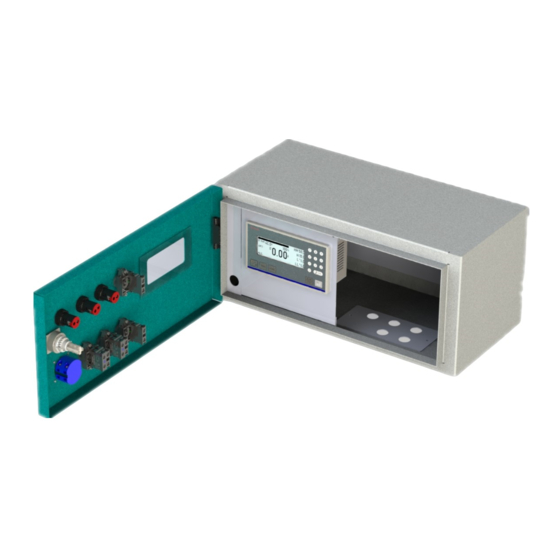
Instruction & Installation
ACU Series LCD Digital Controller
Inner View for ACU Control
ACU Series LCD Digital Controller
Advertisement

Related Manuals for Bosch Rexroth ACU Series


Summary of Contents for Bosch Rexroth ACU Series
- Page 1 ACU Series LCD Digital Controller Please check that the delivered product is the correct item as you ordered. Please do not begin operating this product until you have read this instruction thoroughly and understand its contents " Notice " * Please ensure the instruction manual is made accessible to the nal user of this instrument ACU V1.0 Instruction &...
-
Page 2: Button Configuration
ACU Series LCD Digital Controller INSTRUCTION MANUAL ACU V1.0 BUTTON CONFIGURATION AT/MT : OPERATION PRESS / LOAD : CYLINDER EXTEND HOME/UNLOAD : CYLINDER RETRACT SETTING/SELECT : SELECTION DATA TO ENTRY : COMFIRM DATA ENTRY KEYPAD :①②③④⑤⑥⑦⑧⑨⓪ esc / DEL : ESCAPE or Delete ⓪... - Page 3 ③ CT100 /5A READ : Real time Value from Current Transducer [ Ampere ] : Additional value to compensate real time value : Subtract is Substraction value to compensate real time value PRESS Button to select/move for edit Parameter Noted : Motor Rating 1.5KW with Full Load Current at [ 3.4ampere] Motor Rating 30KW with Full Load Current at [ 54ampere] Enter the Data Number with Keypad ①②③④⑤⑥⑦⑧⑨⓪...
Need help?
Do you have a question about the Rexroth ACU Series and is the answer not in the manual?
Questions and answers