Sign In
Upload
Manuals
Brands
Keysight Technologies Manuals
Accessories
EL30000 Series
Keysight Technologies EL30000 Series Manuals
Manuals and User Guides for Keysight Technologies EL30000 Series. We have
1
Keysight Technologies EL30000 Series manual available for free PDF download: User Manual
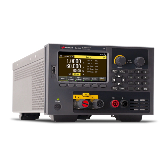
Keysight Technologies EL30000 Series User Manual (141 pages)
DC Electronic Loads
Brand:
Keysight Technologies
| Category:
Accessories
| Size: 10.8 MB
Table of Contents
Table of Contents
2
Notices
6
Copyright Notice
6
Manual Part Number
6
Edition
6
Published by
6
Warranty
6
Technology Licenses
6
U.S. Government Rights
7
Third Party Licenses
7
Waste Electrical and Electronic Equipment (WEEE)
7
Declarations of Conformity
7
Safety Information
8
Safety and Regulatory Information
9
Safety Considerations
9
Safety Symbols
12
Regulatory Markings
13
South Korean Class a EMC Declaration
13
Safety and EMC Requirements
13
Environmental Conditions
14
1 Getting Started
15
Product Introduction
16
Front Panel at a Glance (EL33133A/EL34143A)
18
Front Panel at a Glance (EL34243A)
19
Rear Panel at a Glance (EL33133A/EL34143A)
20
Rear Panel at a Glance (EL34243A)
21
Meter View
22
Data Logger View
24
Scope View
25
Dimension Diagram
26
Setup the Instrument
26
Prepare Instrument for Use
27
Initial Inspection
27
Standard Shipped Items
27
Documentation and Firmware Revisions
27
Recommended Calibration Interval
27
Load Operating Modes
28
CC Mode
28
CV Mode
29
CP Mode
29
CR Mode
30
Programming Ranges
31
Installation
33
Connecting the Power Cord
33
Connecting the Inputs
34
Parallel Connections (EL34243A Only)
37
4-Wire Sense Connection
39
Interface Connections
41
Installing the Optional GPIB Interface (EL34143A and EL34243A Only)
45
Rack Mounting the Instrument
46
Remote Interface Configuration
47
Keysight IO Libraries Suite
47
GPIB Configuration
47
LAN Configuration
48
Using Sockets
52
More about IP Addresses and Dot Notation
53
Remote Control
54
Web Interface
54
Technical Connection Details
56
Use the Built-In Help System
57
View the Help Information for the Front Panel Key
57
View the List of Help Topics
57
Firmware Update
59
Front Panel Menu Reference
60
2 General Operating Information
61
Turning the Unit on
62
Using the Front Panel Knobs
63
View the Error Log
63
Controlling the Inputs
64
Step 1 - Select an Input (EL34243A Only)
64
Step 2 - Set the Load Operating Mode
64
Step 3 - Set the Input Voltage, Current, Resistance, or Power
64
Step 4 - Enable the Input
65
Step 5 - View the Input Voltage and Current
65
Using the Protection Function
67
Protection Function
67
Configuring Protection
67
Clears OVP, OCP and OPP Event
69
Specifying 2-Wire or 4-Wire Sense
70
Configuring the Input Turn-On/Turn-Off Sequence
71
Step 1 - Set the Input Voltage, Current, Power or Resistance of the Input Channels
71
Step 2 - Configure the Turn-On Turn-Off Delays
71
Step 3 - Coupling Selected Inputs
71
Step 4 - Use the All Inputs on and off Keys
71
Specifying the Load Operating Mode
73
Configuring the Load Settings
74
Operating Modes
74
Specifying the Operation Mode (EL34243A Only)
78
Using the Digital Control Port
79
Bi-Directional Digital IO
79
Digital Input
81
Fault Output
81
Inhibit Input
82
Fault/Inhibit System Protection
83
Trigger Input
84
Trigger Output
85
Input Couple Controls
86
Using the Sequencer Function (EL34143A and EL34243A Only)
88
LIST Mode
88
Step 1- Add/Remove Steps To/From the LIST
88
Step 2 - Configure the Input Sequence
89
Step 3 - Run the Input Sequence List
91
Continuous Mode
93
Step 1- Configure the Sequence Properties
93
Step 2 - Run the Input Sequence
94
Pulse Mode
96
Step 1- Configure the Sequence Properties
96
Step 2 - Run the Input Sequence
97
Toggle Mode
99
Step 1- Configure the Sequence Properties
99
Step 2 - Run the Input Sequence
100
Using the Data Logger Function
101
Logging Data
101
Step 1 - Set the Load Operating Mode to CC
101
Step 2 - Program the Input Current Values
101
Step 3 - Program the Sequence for the Input Channels
101
Step 4 - Configure the Data Logger Traces
102
Step 5 - Configure the Data Logger Properties
102
Step 6 - Configure and Enable the DUT Output Accordingly
103
Step 7 - Turn on Input 1, Start the Sequencing and Log the Data
103
Step 8 - Export the Data
103
Data Logger View
105
Data Logger Marker View
106
Using the Knob in Data Logger View
107
Data Logger Properties and Waveform Settings
108
Save the Data Log
112
Using the Scope Function
115
Making Measurement
115
Step 1 - Set the Load Operating Mode to CC
115
Step 2 - Program the Input Current Values
115
Step 3 - Configure the Input Turn-On Sequence
115
Step 4 - Configure the Scope View Traces
116
Step 5 - Configure the Scope Properties
116
Step 6 - Configure and Enable the DUT Output Accordingly
117
Step 7 - Turn on the Inputs and Measure the Current
117
From the Remote Interface
117
Scope View
118
Scope Marker View
120
Using the Knob in Scope View
121
Scope Properties and Waveform Settings
122
Scope Marker Properties
125
Save the Scope Data
125
Locking/Unlocking the Front Panel
126
Capturing a Screen
126
Utilities Menu
127
Utilities Menu - Store and Recall State
127
Store Settings
128
Recall Settings
129
Power on Setting
130
Set to Defaults
130
Utilities Menu - I/O Configuration
131
LAN Settings
131
Digital IO
132
GPIB (Optional)
132
Utilities Menu - Test / Setup
133
Calibration
133
Self-Test
133
User Settings
134
Low Range
135
Help
135
Utilities Menu - Error
137
Utilities Menu - Manage Files
138
Action
138
Browse
139
File Name
139
3 Characteristics and Specifications
140
Advertisement
Advertisement
Related Products
Keysight Technologies EL33133A
Keysight Technologies EL34143A
Keysight Technologies EL34243A
Keysight Technologies E9300A
Keysight Technologies E9300H
Keysight Technologies E9322A
Keysight Technologies E9325A
Keysight Technologies E9323A
Keysight Technologies E9326A
Keysight Technologies E9301B
Keysight Technologies Categories
Measuring Instruments
Test Equipment
Control Unit
Portable Generator
Power Supply
More Keysight Technologies Manuals
Login
Sign In
OR
Sign in with Facebook
Sign in with Google
Upload manual
Upload from disk
Upload from URL