Table of Contents
Advertisement
Available languages
Available languages
Quick Links
NOTICE D'INSTRUCTIONS
OPERATING INSTRUCTIONS
MONTAGE / MISE EN SERVICE / UTILISATION / MAINTENANCE
INSTALLATION / COMMISSIONING / OPERATING / MAINTENANCE
(à fournir à l'utilisateur final pour compléter le dossier d'exploitation requis pendant toute la durée de vie de l'appareil)
(must be given to the end user in order to complete the operating manual during the equipment service life)
GROUPE DE CONDENSATION GCV
COMPRESSEURS OCTAGON
CONDENSING UNIT GCV
OCTAGON COMPRESSORS
Groupe de Fluide DESP : 2 / PED fluid group : 2
Il est impératif de prendre connaissance de ces instructions dès réception de l'appareil et avant toute intervention sur celui-ci.
Notre service technique reste à votre entière disposition au
33 04 42 18 05 00 pour toutes précisions supplémentaires.
These operating instructions must be read at the delivery of the equipment and prior any operation on it.
Our technical department is at your disposal for any additional information (Tel : ++ 33 4 42 18 05 00).
This document is a translation of the French original version which prevails in all cases.
Advertisement
Chapters
Table of Contents

Related Manuals for Profroid GCV


Summary of Contents for Profroid GCV
- Page 1 (à fournir à l’utilisateur final pour compléter le dossier d’exploitation requis pendant toute la durée de vie de l’appareil) (must be given to the end user in order to complete the operating manual during the equipment service life) GROUPE DE CONDENSATION GCV COMPRESSEURS OCTAGON...
- Page 2 La durée de vie prise en compte pour la conception de nos appareils est au minimum de 10 ans sous condition de respecter cette notice d’instructions. La responsabilité de Profroid ne saurait être engagée en cas de manquement aux respects des préconisations de cette notice. Les tuyauteries de raccordement des appareils Profroid sont de différents types : en cuivre, suivant norme NF EN 12735 en acier, suivant norme NF EN 10216-2 (nuance P265GH ;...
- Page 3 éviter tout risque de brûlure ou de gelure. Profroid n’est pas informé de l’utilisation réelle des quasi machines ; leurs intégrations et leurs usages doivent être conformes à la Directive Machines et aux recommandations de cette notice.
- Page 4 S’il y a changement de modèle et/ou de marque, alors le personnel en charge de ce remplacement devra réaliser une note de calcul suivant l’EN 13136 et/ou s’adresser à Profroid s’il n’a pas les éléments de détermination. Manœuvrer régulièrement les vannes de l’appareil pour ne pas qu’elles se bloquent.
- Page 5 REACH Pour les composants DANFOSS (KVP, KVL, KVR, KVD), éviter tout contact entre la peau et le joint torique. Pour les composants DANFOSS (ETS, KVS, SGN, SGP). Eviter tout contact entre la peau et le papier. Eviter de respirer la poussière issue du papier. Recycler le papier comme déchet dangereux. ...
- Page 6 The contractor or the company in charge of the installation shall be responsible for carrying out the required instructions. Profroid disclaims any responsibility for change(s) or repair(s) on its devices made without its prior agreement. The devices are exclusively intended for professionals, for refrigeration purposes and for their limits of use.
- Page 7 When operating, surface temperatures above 60°C and /or below 0°C may be reached. During any servicing operation, the personnel should be extremely careful while working on the device. Profroid is not informed to real use of partly completed machines; their integrations and use must comply to Machines Directive and recommendations of this operating instructions.
- Page 8 The periodic technical checks must be made following frequencies determined by standards, sound engineering practice, end user and installer. Report periodic checks and analyze the data. In case of abnormalities or inconsistencies, determine the cause and correct it. In case of hanged units (evaporator as an example), it is necessary to define an exclusion zone on the ground, to avoid the presence of persona under the equipment.
- Page 9 REACH Concerning the DANFOSS components (KVP, KVL, KVR, KVD), avoid any contact between the skin and the O‐ring Concerning the DANFOSS components (ETS, KVS, SGN, SGP). Avoid any contact between the skin and the paper. Avoid to breathe dust that might come from the paper. Recycle the paper as hazardous waste. ...
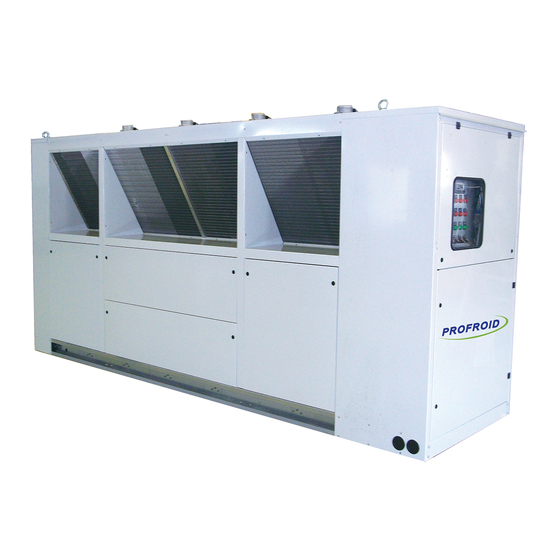
- Page 10 Unités de condensation à air monoblocs carrossées, conçues pour une installation à l'extérieur et composées principalement de: 2 à 4 compresseurs OCTAGON BITZER. 1 condenseur à air PROFROID batteries en V et motoventilateurs hélicoïdes, placé au-dessus du compartiment compresseurs. 1 réservoir de liquide avec soupape de sécurité...
- Page 11 RACCORDEMENT FRIGORIFIQUE AU RESEAU RÉALABLEMENT À TOUTE INTERVENTION SUR LE CIRCUIT FRIGORIFIQUE ON EXPULSERA LA CHARGE D ATTENTE Le tube (cuivre ou acier) utilisé doit être de qualité frigorifique et conforme à la DESP 2014/68/UE. Toutes les tuyauteries de raccordement doivent être correctement supportées et fixées, et en aucun cas ne doivent contraindre celles du groupe.
- Page 12 Il est interdit d'adjoindre à l'huile un détecteur de fuites type colorant ou traceur U.V. Fluide BITZER R404A BSE 32 ou Artic EAL 32 Ce tableau n'est pas exhaustif, mais résume les principales huiles utilisées. Pour l'utilisation d'une autre huile, nous vous conseillons de contacter PROFROID ou le constructeur du compresseur. 10/21...
- Page 13 Remplissage fluide frigorigène Un remplissage en phase liquide est possible lorsque l'installation est sous vide, par la vanne sur le réservoir de liquide ou par la vanne de charge prévue sur le couvercle du déshydrateur (suivant modèles) Essais et préréglages des sécurités Pressostats de sécurité...
- Page 14 ENTRETIEN Les instructions ou recommandations constructeur devront être respectées impérativement et nos services techniques restent à votre disposition pour toutes informations. Tous les mois, on vérifiera: - Les points de coupure des pressostats de sécurité HP/BP - Les pressions et les températures de chaque compresseur. - Le cycle de pump down, - Les niveaux d'huile, - L'humidité...
- Page 15 DEPANNAGE Exemples de pannes et solutions DEFAUT CAUSE PROBABLE REPARATION 1. Température Trop de surchauffe du gaz d'aspiration Examiner et régler les détendeurs thermostatiques d'aspiration trop (supérieur à 20K) des évaporateurs. haute 2. Température Liquide dans conduite d'aspiration. Régler les détendeurs thermostatiques. Contrôler et replacer si nécessaire les bulbes sur d'aspiration trop Bulbe desserré...
- Page 16 DEFAUT CAUSE PROBABLE REPARATION Enclenchement des ventilateurs mal ajusté si Ajuster pressostat. 7. Pression de condensation à air. condensation trop basse Surchauffe trop importante à l'aspiration. Règles les détendeurs thermostatiques. 8. Température refoulement trop haute 9. Température Surchauffe à l'aspiration trop importante. Vérifier et régler les détendeurs thermostatiques.
- Page 17 Packaged air condenser units, designed for installation outdoors and consisting primarily of: 2 to 4 OCTAGON BITZER compressors 1 PROFROID air condenser V Type with helicoid fans (condenser above compressors compartment) 1 liquid receiver with safety valve 1 electrical cabinet...
- Page 18 REFRIGERATION NETWORK CONNECTION EFORE ANY WORK IS DONE ON THE REFRIGERATION CIRCUIT THE HOLDING CHARGE MUST BE REMOVED The piping used (copper or steel) must be of refrigeration quality in accordance with PED 2014/68/EU. All piping must be correctly supported and fixed and should in no case be allowed to restrict the piping of the power pack. The units are provided with a temporary charge of neutral gas (nitrogen or dry air) which should be removed before any operation (connection by welding).
- Page 19 Artic EAL 32 This table is not exhaustive, but summarises the principal oils used. If any other oil is to be used, we would advise contacting PROFROID or the compressor manufacturers. RefrigerantFluidCharge It is possible to charge in liquid phase when the installation is under vacuum through the charging valve provided on the liquid receiver (depending on models).
- Page 20 The charging bottle must remain connected to this valve permanently during the whole start-up period to enable instant adjustment while charging the installation. Pre-Setting And Checking of SafetySystems Test the oil level monitoring type OLCK1 (for compressors fitted with) Check the time delay : After compressor start: 90s In operation 5s Check the actual cut-off if oil pressure drops.
- Page 21 MAINTENANCE Instructions or recommendations appearing in the various technical advice notes and manufacturer's service manuals should be followed precisely; please contact our Technical Department for any additional information. Every month, check: Safety cut-off points of HP/LP safety pressure switches Pressures and temperatures in each compressor. Pump down cycle, Cut-in of safety pressure switches in condenser fans, Oil levels...
- Page 22 TROUBLESHOOTING Examples of faults and solutions FAULT PROBABLE CAUSE ACTION REQUIRED 1. Suction Too much suction gas superheat Examine and adjust the thermostatic expansion (above 20K) valves in the evaporators. Temperature too high 2. Suction Liquid in the suction line. Adjust thermostatic expansion valves.
- Page 23 FAULT PROBABLE CAUSE ACTION REQUIRED 14. Abnormal Bolts loose. Tighten bolts Noise in Internal mechanical failure Do not re-start compressor Check and re-set thermostatic expansion valves. Compressor Fluid in suction line Check that the liquid solenoid valves do not remain open when machine stops.
- Page 24 SEPR 33 315 1,86 8,30 5,48 0,70 6,18 1,35 9,34 5,29 0,70 5,99 1,56 GCV B2SH4EES04 3MS/2V R404A GCV B2SH4EES04 3MS/2V SI R404A SEPR 33 315 1,86 8,30 5,48 0,70 6,18 1,35 9,34 5,29 0,70 5,99 1,56 GCV B2SH4DES05 3MS/2V R404A...
- Page 25 (kW) (kW) (kW) SEPR 10,74 4,89 0,70 5,59 1,93 12,04 4,34 0,70 5,04 2,39 0,25 GCV B2SH4EES04 3MS/2V R404A GCV B2SH4EES04 3MS/2V SI R404A SEPR 10,74 4,89 0,70 5,59 1,93 12,04 4,34 0,70 5,04 2,39 0,25 SEPR 12,80 5,93 0,70...
- Page 26 Declared Declared Declared Declared Declared Declared Designation (kW) (kW) (kW) (kW) (kW) (kW) (kW) (kW) GCV B2SH4EES04 3MS/2V H N P SEPR 8,92 4,12 0,70 4,82 1,86 10,20 4,14 0,70 4,84 2,11 0,25 GCV B2SH4DES05 3MS/2V H N P SEPR...
- Page 27 (kW) (kW) (kW) SEPR 9,03 4,13 0,70 4,83 1,87 10,33 4,16 0,70 4,86 2,13 0,25 GCV B2SH4EES04 3MS/2V H N P GCV B2SH4DES05 3MS/2V H N P SEPR 10,47 4,88 0,70 5,58 1,88 12,04 4,59 0,70 5,29 2,28 0,25 SEPR...
- Page 28 10,49 2,64 SEPR 43424 3,63 25,58 10,09 0.76 10,85 2,36 28,59 9,25 0.76 10,01 2,86 GCV R2SH4EES04 3MS/2V SI R404A GCV R2SH4EES06 3MS/3V R404A SEPR 44595 3,61 26,16 9,57 1,40 10,97 2,39 29,24 8,78 1,40 10,18 2,88 GCV R2SH4EES06 3MS/3V SI R404A...
- Page 29 0,25 GCV R2SH4EES04 3MS/2V R404A SEPR 32,77 7,86 0.76 8,62 3,81 36,79 6,24 0.76 7,00 5,26 0,25 GCV R2SH4EES04 3MS/2V SI R404A GCV R2SH4EES06 3MS/3V R404A SEPR 33,49 7,43 1,40 8,83 3,80 37,54 5,84 1,40 7,24 5,19 0,25 GCV R2SH4EES06 3MS/3V SI R404A...
- Page 30 SEPR 45104 3,23 23,64 9,54 0.96 10,50 2,26 26,11 8,83 0.96 9,79 2,67 GCV R2SH4EES04 3MS/2V H N P GCV R2SH4EES04 3MS/2V SI H N P SEPR 42523 3,54 24,43 9,32 0.76 10,08 2,43 26,94 8,57 0.76 9,33 2,89 GCV R2SH4EES06 3MS/3V H N P...
- Page 31 GCV R2SH4EES04 3MS/2V H N P SEPR 29,64 7,68 0.96 8,64 3,43 33,14 6,49 0.96 7,45 4,45 0,25 GCV R2SH4EES04 3MS/2V SI H N P SEPR 30,53 7,39 0.76 8,15 3,75 34,05 6,17 0.76 6,93 4,92 0,25 GCV R2SH4EES06 3MS/3V H N P...
- Page 32 GCV R2SH4EES04 3MS/2V H N P SEPR 42790 3,30 23,00 9,26 0,96 10,22 2,25 25,58 8,53 0,96 9,49 2,70 GCV R2SH4EES04 3MS/2V SI H N P SEPR 40568 3,60 23,77 9,05 0,76 9,81 2,42 26,38 8,29 0,76 9,05 2,91 GCV R2SH4EES06 3MS/3V H N P...
- Page 33 4,63 0,25 SEPR 30,10 7,10 0,76 7,86 3,83 33,76 5,89 0,76 6,65 5,08 0,25 GCV R2SH4EES04 3MS/2V SI H N P SEPR 30,83 6,84 1,44 8,28 3,72 34,45 5,67 1,44 7,11 4,85 0,25 GCV R2SH4EES06 3MS/3V H N P GCV R2SH4EES06 3MS/3V SI H N P...
- Page 34 NOTICE D’INSTRUCTIONS GENERALE POUR V3.0 COFFRETS ET ARMOIRES ELECTRIQUES Page 1 / 51 fournir à l’utilisateur final pour compléter dossier d’exploitation pendant toute la durée de vie de l’appareil) COFFRETS et ARMOIRES ELECTRIQUES LIVRES RACCORDES OU SEPARES POUR 1/18 PRODUITS COMPRESSORISES & ECHANGEURS...
- Page 35 NOTICE D’INSTRUCTIONS GENERALE POUR V3.0 COFFRETS ET ARMOIRES ELECTRIQUES Page 2 / 51 Il est impératif de prendre connaissance de ces instructions dès réception de l’équipement et avant toute intervention sur celui-ci. Notre service technique reste à votre entière disposition au 33 04 42 18 05 00 pour toutes précisions supplémentaires.
-
Page 36: Table Of Contents
NOTICE D’INSTRUCTIONS GENERALE POUR V3.0 COFFRETS ET ARMOIRES ELECTRIQUES Page 3 / 51 SOMMAIRE TERMINOLOGIE ......................................2 RECOMMANDATIONS DE SECURITE ..............................3 RECEPTION DU MATERIEL ..................................6 TRANSPORT ET MANUTENTION ................................7 MONTAGE & INSTALLATION................................. 8 PRESENTATION GENERALE ..................................9 •... -
Page 37: Recommandations De Securite
NOTICE D’INSTRUCTIONS GENERALE POUR V3.0 COFFRETS ET ARMOIRES ELECTRIQUES Page 4 / 51 RECOMMANDATIONS DE SECURITE Très important : avant toute intervention sur un équipement, l'alimentation électrique doit être coupée. Il appartient à l'intervenant d'effectuer les consignations necessaires. Attention : Certains équipements contenant des condensateurs peuvent conserver une charge élevée même hors tension (variateurs de fréquences, démarreurs progressifs…) Attention : Dans certains coffrets / armoires, une partie des équipements peut être alimentée par une alimentation externe. - Page 38 à distance de l’alimentation générale de l’armoire par les services de secours si besoin. Profroid dégage toute responsabilité en cas de modification(s) ou de réparation(s) de ses appareils sans son accord préalable. Les appareils sont exclusivement destinés à des professionnels, pour un usage en réfrigération et dans leurs limites d’utilisation.
- Page 39 Ceci est également valable pour les phases d’arrêt de l’installation. La responsabilité de Profroid ne saurait être engagée en cas de manquement aux respects des préconisations de cette notice. Toute modification coffret / armoire réalisée par l’installateur, l’exploitant ou ses sous-traitants doit l’être dans le respect des : Règles de mise en œuvre...
- Page 40 établir des réserves sur le récépissé de transport et les confirmer par lettre avec accusé de réception sous 48 heures au transporteur avec une copie à PROFROID. Si la livraison ne correspond pas à votre commande contacter PROFROID.
-
Page 41: Transport Et Manutention
NOTICE D’INSTRUCTIONS GENERALE POUR V3.0 COFFRETS ET ARMOIRES ELECTRIQUES Page 8 / 51 TRANSPORT ET MANUTENTION Les opérations de chargement et déchargement doivent être réalisées avec les matériels adéquats (chariot, grue…) en utilisant les éventuels points de levage prévus à cet effet. Les coffrets / armoires électriques sont équipés, lorsque nécessaire, de perçages obturés par des bouchons permettant de monter des œillets de levage ou directement d’œillets de levage, en partie haute de l’enveloppe pour le levage ou manutention à... -
Page 42: Montage & Installation
NOTICE D’INSTRUCTIONS GENERALE POUR V3.0 COFFRETS ET ARMOIRES ELECTRIQUES Page 9 / 51 MONTAGE & INSTALLATION Si le coffret ou l’armoire est destiné à rester positionné sur le châssis de la machine, l’installateur veillera à retirer les renforts provisoires et autres jambes de forces éventuelles uniquement destinées au transport, afin que ces éléments ne créent pas de contraintes ou de vibrations nuisibles en fonctionnement. -
Page 43: Presentation Generale
Le schéma électrique comporte : - En page de garde OP1 : Au centre : Le nom du chantier /client si communiqué à Profroid. Dans le cartouche le N°AR à utiliser comme identifiant de l’affaire lors de tout échange avec Profroid. -
Page 44: Compatibilite Electromagnetique
COMPATIBILITE ELECTROMAGNETIQUE Profroid attache la plus grande importance à la mise en œuvre de ses coffrets et armoires, notamment d’un point de vue CEM, pour les équipements perturbateurs ou sensibles. Un équipement perturbateur peut générer des perturbations électromagnétiques (émises et conduites) : variateur de fréquence ou démarreur progressif, par exemple. - Page 45 NOTICE D’INSTRUCTIONS GENERALE POUR COFFRETS ET ARMOIRES ELECTRIQUES L’installateur devra accorder la plus grande importance à la mise en œuvre des câbles des équipements perturbateurs et des équipements sensibles aussi bien au niveau des raccordements (tenant et aboutissant) qu’au niveau du cheminement. Les câbles perturbateurs ou sensibles devront être de type blindé.
-
Page 46: Raccordement Electrique Au Reseau
NOTICE D’INSTRUCTIONS GENERALE POUR COFFRETS ET ARMOIRES ELECTRIQUES RACCORDEMENT ELECTRIQUE AU RESEAU ’ E REFÉRER AU SCHÉMA ÉLECTRIQUE ET À LA NOTICE D UTILISATION FOURNIS -Toute intervention d’ordre «électrique » doit se faire en ayant au préalable coupé et consigné l’alimentation électrique ou les alimentations électriques, par du personnel dûment formé... -
Page 47: Raccordements Electriques Des Actionneurs Et Capteurs
NOTICE D’INSTRUCTIONS GENERALE POUR COFFRETS ET ARMOIRES ELECTRIQUES RACCORDEMENTS ELECTRIQUES DES ACTIONNEURS ET CAPTEURS ’ E REFÉRER AU SCHÉMA ÉLECTRIQUE ET À LA NOTICE D UTILISATION FOURNIS Le coffret / armoire est conçu selon les normes EN60204-1; EN61000-6; NF-C-15-100; Tout câblage sur site doit être conforme à ces mêmes normes ainsi qu’aux normes légales en vigueur dans le pays concerné. - Page 48 NOTICE D’INSTRUCTIONS GENERALE POUR COFFRETS ET ARMOIRES ELECTRIQUES 14/18...
-
Page 49: Auxiliaires De Controle Et De Securite
NOTICE D’INSTRUCTIONS GENERALE POUR COFFRETS ET ARMOIRES ELECTRIQUES AUXILIAIRES DE CONTROLE ET DE SECURITE Les sécurités équipant l’installation (pressostat HP,BP,système de contrôle du sens de rotation du moteur, limiteur de température de refoulement et controleur de niveau d'huile) nécessitent un réglage en fonction de chaque installation, avant la mise en service de l’installation. -
Page 50: Principe De Fonctionnement
NOTICE D’INSTRUCTIONS GENERALE POUR COFFRETS ET ARMOIRES ELECTRIQUES PRINCIPE DE FONCTIONNEMENT É É É É Chaque compresseur est autorisé à fonctionner au travers d’une chaine de sécurité mettant en œuvre tous les organes de sécurité nécessaires. En fonction des options de la machine, on pourra par exemple trouver : Contact télécommande M/A , Kriwan (module de sécurité... - Page 51 NOTICE D’INSTRUCTIONS GENERALE POUR COFFRETS ET ARMOIRES ELECTRIQUES Rappel : Les différentes temporisations présentes dans les coffrets et armoires doivent être réglées avant la mise en route Les constructeurs de compresseurs imposent un nombre limité de démarrages par heure. Pour satisfaire à...
-
Page 52: Principe De Regulation
NOTICE D’INSTRUCTIONS GENERALE POUR COFFRETS ET ARMOIRES ELECTRIQUES D’une manière assez générale, la séquence de fonctionnement d’une machine compressorisée destinée à la réfrigération sera la suivante : Le système de pilotage de l’installation (pressostatique ou électronique) démarrera la mise en route des différents compresseurs les uns après les autres en fonction de la charge de réfrigération demandée par l’installation (chambres froides, meubles…) Dans les cas où... -
Page 53: Moteurs À Commutation De Pôles
NOTICE D’INSTRUCTIONS GENERALE POUR COFFRETS ET ARMOIRES ELECTRIQUES É É Cas général : Le système de pilotage de l’installation (pressostatique ou électronique) démarrera la mise en route des différents ventilateurs de condenseur par étages, en fonction de la pression de condensation. -
Page 54: Postes Froids
NOTICE D’INSTRUCTIONS GENERALE POUR COFFRETS ET ARMOIRES ELECTRIQUES É É É É Une information sous la forme d’une synthèse sur bornier des ‘n’ contacts représentatifs de la disponibilité des compresseurs, est mise à la disposition de l’installateur final pour asservir ses VEM. Celui-ci doit utiliser cet asservissement et le câbler pour arrêter ses VEM postes de froid. -
Page 55: Operations De Mise En Service
NOTICE D’INSTRUCTIONS GENERALE POUR V3.0 COFFRETS ET ARMOIRES ELECTRIQUES Page 20 / 51 OPERATIONS DE MISE EN SERVICE Avant d'effectuer le branchement électrique, s'assurer que la tension et la fréquence du réseau d'alimentation correspondent aux indications figurant sur les schémas en page OP 10 . Tout câblage sur site doit être conforme aux normes légales en vigueur dans le pays d’installation (y compris : mise à... - Page 56 Vérification des paramètres en accord avec la fiche de paramétrage présente dans les schémas électriques Profroid. Attention, cette liste de paramètres est proposée à titre indicatif et n’engage pas la responsabilité de Profroid. Il appartient à l’installateur d’adapter les paramètres de régulation à chaque...
-
Page 57: Essais Et Pré-Réglages Des Sécurités
• Attention, dans les installations Profroid, l’application présente dans le variateur est le plus souvent une application développée par Profroid. Ne pas réinitialiser le variateur et ne pas revenir aux paramètres usine, vous perdriez tout le paramétrage spécifique Profroid (plusieurs dizaines de paramètres). -
Page 58: Sens De Rotation Moteurs
NOTICE D’INSTRUCTIONS GENERALE POUR V3.0 COFFRETS ET ARMOIRES ELECTRIQUES Page 23 / 51 Avant la mise en route de l’installation, il faut vérifier les sens de rotation des moteurs déterminer le raccordement des phases aux borniers du compresseur) Attention : Les compresseurs à... -
Page 59: Entretien & Maintenance
NOTICE D’INSTRUCTIONS GENERALE POUR V3.0 COFFRETS ET ARMOIRES ELECTRIQUES Page 24 / 51 ENTRETIEN & MAINTENANCE • Très important : avant toute intervention sur un équipement, l'alimentation électrique doit être coupée. Il appartient à l'intervenant (installateur, sous-traitant, exploitant) d'effectuer les consignations nécessaires. •... - Page 60 NOTICE D’INSTRUCTIONS GENERALE POUR V3.0 COFFRETS ET ARMOIRES ELECTRIQUES Page 25 / 51 • Les vérifications techniques périodiques doivent être effectuées suivant les fréquences déterminées par les normes, les bonnes pratiques de la profession, l’exploitant et l’installateur. • Assurer le relevé des vérifications périodiques et analyser les données. En cas d’anomalies ou d'incohérences, déterminer la cause et y remédier.
- Page 61 NOTICE D’INSTRUCTIONS GENERALE POUR V3.0 COFFRETS ET ARMOIRES ELECTRIQUES Page 26 / 51 INSTRUCTIONS MANUAL FOR ELECTRICAL PANELS: MOUNTING COMMISSIONING USING MAINTAINING (This document must be delivered to the final user in the aim complete technical files during whole life of the installation.) CONTROL BOXES &...
- Page 62 NOTICE D’INSTRUCTIONS GENERALE POUR V3.0 COFFRETS ET ARMOIRES ELECTRIQUES Page 27 / 51 It is essential to read these instructions upon receipt of the equipment and before working on it. Our technical department stays at your disposal for any further information 27/1...
- Page 63 NOTICE D’INSTRUCTIONS GENERALE POUR V3.0 COFFRETS ET ARMOIRES ELECTRIQUES Page 28 / 51 SUMMARY 1) TERMINOLOGY ........................................ 28 SAFETY RECOMMENDATIONS ................................29 RECEIPT OF MATERIAL ..................................32 TRANSPORT AND HANDLING ................................33 MOUNTING AND INSTALLING ................................34 GENERAL PRESENTATION ..................................35 •...
- Page 64 NOTICE D’INSTRUCTIONS GENERALE POUR V3.0 COFFRETS ET ARMOIRES ELECTRIQUES Page 29 / 51 SAFETY RECOMMENDATIONS Very important : before working on the equipment, the main power supply must be powered OFF. It is up to the technician to make the necessary consignments. Warning : Some equipments which contain condensators may remain electrically loaded even after power off (frequency converters, soft starters…) Warning : In some control panels, part of the equipments can be powered by an external supply.
- Page 65 OFF function of the main power supply. Profroid disclaims all liability in case of modification(s) or repair action(s) done in case of modifications or repair of these equipments without prior consent.
- Page 66 This is also true for the stop phases of the installation. Profroid is not liable in case of non respect of the recommendations of this document. Any modification on the control panels, done by the operator, the installer, or their sub-contractors must be done in the respect...
-
Page 67: Receipt Of Material
If issues are found, if the control panel is damaged or not complete, reserves must be declared on transport documents and confirmed within 48 hours to the transporter, copy to Profroid. If the delivery does not correspond to your order, please contact Profroid. -
Page 68: Transport And Handling
NOTICE D’INSTRUCTIONS GENERALE POUR V3.0 COFFRETS ET ARMOIRES ELECTRIQUES Page 33 / 51 TRANSPORT AND HANDLING Loading and unloading operations must be done with appropriate equipments (forklift, crane…), using the lifting points especially made for this. The control panels are equipped, when necessary, with holes closed by caps, which can be used to mount lifting rings, at the top of the enclosure. -
Page 69: Mounting And Installing
NOTICE D’INSTRUCTIONS GENERALE POUR V3.0 COFFRETS ET ARMOIRES ELECTRIQUES Page 34 / 51 MOUNTING AND INSTALLING If the control panel is meant to stay on the machine frame, the installer will have to remove the temporary reinforcements and other struts only mounted for transport, to avoid those features to create some stress or harmful vibrations when the machine will run. -
Page 70: General Presentation
- On page OP1 : At the center : Site / Customer name. At the bottom, the AR Number to use as job reference for any exchange with Profroid. - On page OP2 and followings : Detailled list of the pages... -
Page 71: Electromagnetic Compatibility
Page 36 / 51 ELECTROMAGNETIC COMPATIBILITY Profroid puts a lot of attention in the manufacturing of its control panels, especially for the EMC, disturbing or sensitive devices. A disturbing device can generate electromagnetic disturbances : frequency converter or soft starter for example. - Page 72 NOTICE D’INSTRUCTIONS GENERALE POUR V3.0 COFFRETS ET ARMOIRES ELECTRIQUES Page 37 / 51 The installer will have to take care about the way to mount and fix the cables for the disturbing and sensitive devices, for the connections as well as for the tracking. Cables for disturbing and sensitive devices will have to be shielded.
-
Page 73: Electrical Connection On Site
NOTICE D’INSTRUCTIONS GENERALE POUR V3.0 COFFRETS ET ARMOIRES ELECTRIQUES Page 38 / 51 ELECTRICAL CONNECTION ON SITE LEASE REFER TO THE ELECTRICAL DIAGRAM AND TO THE USING MANUAL -Any work at the electrical equipment must be done by having previously powered OFF the main supply or the main supplies, by authorized people. -
Page 74: Actuator And Sensors Connections
NOTICE D’INSTRUCTIONS GENERALE POUR V3.0 COFFRETS ET ARMOIRES ELECTRIQUES Page 39 / 51 ACTUATOR AND SENSORS CONNECTIONS REFER TO THE ELECTRICAL DIAGRAM AND TO THE INSTRUCTION MANUAL The control panel is defined according to the standards EN60204-1; EN61000-6; NF-C-15-100; Any wiring modification on site must be in compliance with those standards and with the legal rules of the country. - Page 75 NOTICE D’INSTRUCTIONS GENERALE POUR V3.0 COFFRETS ET ARMOIRES ELECTRIQUES Page 40 / 51 40/1...
-
Page 76: Control And Security Auxiliaries
NOTICE D’INSTRUCTIONS GENERALE POUR V3.0 COFFRETS ET ARMOIRES ELECTRIQUES Page 40 / 51 CONTROL AND SECURITY AUXILIARIES - Securities of the installation (HP & LP pressure switches, motor rotation direction control system, discharge temperature switch and oil level controller) need to be adjusted according to each installation features, before any start of the installation.. -
Page 77: Operating Principle
NOTICE D’INSTRUCTIONS GENERALE POUR V3.0 COFFRETS ET ARMOIRES ELECTRIQUES Page 41 / 51 OPERATING PRINCIPLE Every compressor is enabled to work through a security chain implementing all necessary security features. According to the machine options, we will find for example: Command contact ON/OFF, Kriwan (compressor thermal security module), Micro-pressure switches,... - Page 78 NOTICE D’INSTRUCTIONS GENERALE POUR V3.0 COFFRETS ET ARMOIRES ELECTRIQUES Page 42 / 51 Reminder: All the timers present in the control panel must be set before starting the installation. Compressors manufacturers impose a limited number of start in one hour. To meet this manufacturer recommendation, control panels are equiped with «...
- Page 79 NOTICE D’INSTRUCTIONS GENERALE POUR V3.0 COFFRETS ET ARMOIRES ELECTRIQUES Page 43 / 51 Generally, the working cycle of a refrigeration compressorized machined destined for refrigeration will be : The command system of the installation (pressostatic or electronic) will start the compressors one after the other, according to the refrigeration load required (cold rooms, cabinets…).
-
Page 80: Controls Principle
NOTICE D’INSTRUCTIONS GENERALE POUR V3.0 COFFRETS ET ARMOIRES ELECTRIQUES Page 44 / 51 In general, the command system of the installation (pressostatic or electronic) will start the condensers fans step by step, according to the condensing pressure. In some installation, motors are driven in speed variation, totally, or partially. ... -
Page 81: Cold Rooms
NOTICE D’INSTRUCTIONS GENERALE POUR V3.0 COFFRETS ET ARMOIRES ELECTRIQUES Page 45 / 51 An information is available on the control panel terminals. It is a chain made with all the representative contacts about compressors availability. This information is supplied to the installer in the aim to enslave liquid valve. The installer must use this feature and wire it to close the liquid valves. -
Page 82: Comissioning Operations
NOTICE D’INSTRUCTIONS GENERALE POUR V3.0 COFFRETS ET ARMOIRES ELECTRIQUES Page 46 / 51 COMISSIONING OPERATIONS Before any electrical connection, ensure that the main supply voltage and frequency correspond to the indications of the electrical diagram page OP 10 . Any wiring done on site must be compliant with official standards of the country (including earthing). - Page 83 • Warning : this list of parameters is proposed as information and Profroid is not liable for any missing tests or checks to be done on site during commissioning. The installer must adapt those settings for each installation.
-
Page 84: Securities Preset And Check
(Automatic mode) • Warning : in Profroid’s installation, in the frequency converter, the software present is most of time a specific application, developped by Profroid. Do never come back to the factory settings, because this will erase this specific application. -
Page 85: Motor Rotation Direction
NOTICE D’INSTRUCTIONS GENERALE POUR V3.0 COFFRETS ET ARMOIRES ELECTRIQUES Page 49 / 51 Before starting the installation, check each motor rotation direction. Warning : Screw compressors have a unique rotation direction. Any reverse rotation, during a time specified by the compressor manufacturer, may cause compressor destruction. In case of modifications of the wiring, upstream of the control panel, all the rotation directions must be checked again. -
Page 86: Maintenance & Repair
NOTICE D’INSTRUCTIONS GENERALE POUR V3.0 COFFRETS ET ARMOIRES ELECTRIQUES MAINTENANCE & REPAIR • Warning : Before any repair on a equipment, ensure the power supply is switched off. The installer or subcontractor must correctly secure the installation. • Warning : Some equipments may contain capacitors and those parts may store an important electrical load, even switched OFF (frequency converters, soft starters…) •... - Page 87 NOTICE D’INSTRUCTIONS GENERALE POUR V3.0 COFFRETS ET ARMOIRES ELECTRIQUES • Periodic audits must be written down on documents, and analysis must be done of those documents to identify causes and solve problems. • Monthly check differential circuit breakers function, with the specific button on it. •...
- Page 88 NOTICE D’INSTRUCTIONS GENERALE POUR V3.0 COFFRETS ET ARMOIRES ELECTRIQUES Manufactured in France byPROFROID CARRIER S.C.S 178, rue du Fauge - ZI Les Paluds - B.P. 1152 - 13782 Aubagne Cedex - France International : Tel. (33) 4 42 18 05 00 - Fax (33) 4 42 18 05 02...
Need help?
Do you have a question about the GCV and is the answer not in the manual?
Questions and answers