Advertisement
Quick Links
4-20mA OUTPUT CURRENT
SENSOR SERIES
Installation & Operation Instructions
PRECAUTIONS
• This product is not intended to be used for
Life or Safety applications.
• This product is not intended for use in any
hazardous or classified locations.
• The A/CTA2 and A/SCTA2 Series Current
Sensors must be used on Insulated
Conductors Only.
HIGH VOLTAGE
• Disconnect and lock out all power sources
before installation as severe injury or death
may result from electrical shock due to
contact with high voltage wires.
GENERAL INFORMATION
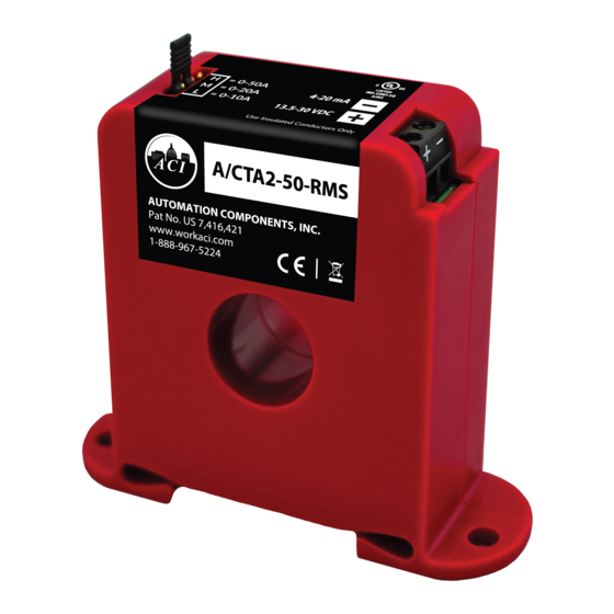
The 4-20 mA Output Analog Current Sensors are designed
for use in any AC current monitoring application in which
you are looking to monitor a particular piece of
equipment. Applications may include monitoring a
resistive type load such as an incandescent light bulb,
heating element as well as any single speed linear load.
For currents monitored above 250 Amps, the CTA2-5 and
SCTA2-5 are ideal for use with a step down Ratio:5A
Output CT (Current Transformer) in stepping down
current in a monitored conductor to a proportional 0 to 5A
output signal. The current sensors are available in both
solid and split-core versions which also includes a
Patented (Pat. No. US 7,416,421) 35 mm Din Rail mounting
foot for easy installation in panel mount applications. The
solid-core versions are a great choice for new installations
or OEM applications in which cost sensitivity, lower trip
points and environmental issues like dust and moisture
may be of concern. The split-core version of the current sensors work great in retro t applications and for use on service
technicians vehicles since one or two parts will work in most applications and can be easily installed without
disconnecting any wires.
INSTALLATION
Make sure that all installations are in compliance with all national and local electrical codes. Only quali ed
individuals that are familiar with codes, standards, and proper safety procedures for high-voltage
installations should attempt installation. The current sensor is a 2-wire, 4 to 20 mA Loop Powered device
Automation Components, Inc.
2305 Pleasant View Road | Middleton, WI 53562
Phone: 1-888-967-5224 | Website: workaci.com
FIGURE 1: DIMENSIONS
Solid-Core
2.36" (59.94mm)
1.03"
(26.16mm)
Split-Core
2.55" (64.69mm)
3.24" (82.23mm)
Page 1
Phone: 1-888-967-5224
Website: workaci.com
2.77"
(70.45mm)
2.87" (72.80mm)
3.35" (84.99mm)
2.77"
(70.35mm)
1.10" (28.02mm)
2.87" (72.77mm)
Version: 8.0
I0000789
Advertisement

Related Manuals for aci A/CTA2 Series


Summary of Contents for aci A/CTA2 Series
- Page 1 4-20mA OUTPUT CURRENT Phone: 1-888-967-5224 SENSOR SERIES Website: workaci.com Installation & Operation Instructions FIGURE 1: DIMENSIONS PRECAUTIONS Solid-Core • This product is not intended to be used for 2.36” (59.94mm) Life or Safety applications. • This product is not intended for use in any hazardous or classified locations.
- Page 2 Note: An extra jumper shunt is included. It can be discarded if not needed. Note: In applications where high vibrations are encountered, ACI recommends to use the jumper shunt without tab. A pliers can help with jumper shunt installation onto the pins.
-
Page 3: Wiring Instructions
WIRING INSTRUCTIONS ACI recommends the use of a two conductor 16 to 22 AWG shielded cable, copper wire only, for all 4 to 20mA current sensor installations. A maximum wire length of less than 30 meters (98.4 feet) should be used between the current sensors and the Building Management System or controller. -
Page 4: Troubleshooting
TROUBLESHOOTING PROBLEM SOLUTION(S) - Con rm that you have +13.5 to 30VDC in series with the current sensor output terminals No reading and the analog input of the control panel. - Check the polarity of the circuit. - Verify that the terminals are screwed down, wires are rmly in place. - Disconnect the input to the control panel and then insert a current meter (mA range) in series with the current sensor output to verify that the circuit is working properly. -
Page 5: Product Specifications
Note : Only the 0 to 100 Amp range in the A/CTA2-250-RMS will meet accuracy speci cations from 15 to 100 Hz WARRANTY The ACI Current Switch Series are covered by ACI’s Five (5) Year Limited Warranty, which is located in the front of ACI’S SENSORS & TRANSMITTERS CATALOG or can be found on ACI’s website: www.workaci.com. - Page 6 NOTES Page 6 Automation Components, Inc. Version: 8.0 2305 Pleasant View Road | Middleton, WI 53562 I0000789 Phone: 1-888-967-5224 | Website: workaci.com...
- Page 7 NOTES Page 7 Automation Components, Inc. Version: 8.0 2305 Pleasant View Road | Middleton, WI 53562 I0000789 Phone: 1-888-967-5224 | Website: workaci.com...
- Page 8 Automation Components, Inc. 2305 Pleasant View Road Middleton, WI 53562 Phone: 1-888-967-5224 Website: workaci.com Page 8 Automation Components, Inc. Version: 8.0 2305 Pleasant View Road | Middleton, WI 53562 I0000789 Phone: 1-888-967-5224 | Website: workaci.com...