
Related Manuals for Venstar EXPLORER RESIDENTIAL T3950-IAQ


Summary of Contents for Venstar EXPLORER RESIDENTIAL T3950-IAQ
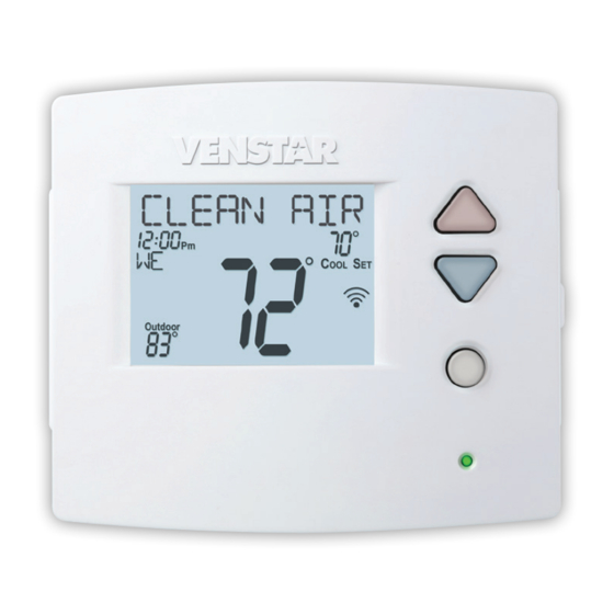
- Page 1 RESIDENTIAL T3950-IAQ DIGITAL THERMOSTAT Up to 4 Heat & 2 Cool Stages With Air Patrol, Humidity Control, & Dual Fuel Capable Owner’s Manual and Installation Instructions HEAT & COOL HEAT PUMP...
- Page 2 5 . 0 5 . 0 T h i s d e v i c e c o mp l i e s w i t h P a r t 1 5 o f t h e F C C R u l e s . O p e r a t i o n i s s u b j e c t t o t h e f o l l o w i n g t w o c o n d i t i o n s : ( 1 ) t h i s d e v i c e ma y n o t c a u s e h a r mf u l i n t e r f e r e n c e , a n d ( 2 ) t h i s d e v i c e mu s t a c c e p t a n y i n t e r f e r e n c e r e c e i v e d , i n c l u d i n g i n t e r f e r e n c e t h a t ma y...
- Page 3 T h i s d e v i c e c o n t a i n s l i c e n c e - e x e mp t t r a n s mi t t e r ( s ) / r e c e i v e r ( s ) t h a t c o mp l y w i t h I n n o v a t i o n , S c i e n c e a n d E c o n o mi c D e v e l o p me n t C a n a d a ’...
-
Page 4: Table Of Contents
Table of Contents GET TO KNOW YOUR THERMOSTAT ................HOW TO USE YOUR THERMOSTAT................AIR PATROL ........................SETUP STEPS - USER SETTINGS Program Mode (non-programmable or 7 day programmable) ........Available Modes (heat only, cool only, heat/cool, auto) ..........Backlight (on/off, intensity, nighttime dimming) ............View equipment runtimes (filter, heat, cool, aux heat, UV, humidifier) ............. - Page 5 Get To Know Your Thermostat Backlit, Scrolling Display Backlit Cooler & Warmer Buttons Backlit LCD Display Mode Button Heat or Cool Demand Indicator Red = Heat, Green = Cool SENSOR Setup Buttons Behind Door...
- Page 6 Get To Know Your Thermostat SENSOR Setup Buttons...
- Page 7 Get To Know Your Thermostat Display Features Program ONOFF 2nd3rd 18:88 Stage Setup Step Day Night Morning Evening Fan On Outdoor Program icon—Indicates that Time Period Programming is running or is enabled to be set. Clock with Day of the Week—Indicates the current time and day. This clock is also used to program the time period schedules.
- Page 8 Get To Know Your Thermostat Display Features Program ONOFF 2nd3rd 18:88 Stage Setup Step Day Night Morning Evening Fan On Outdoor 2nd and 3rd Stage icons Indicates what stage of cooling or heating is currently energized. Setup Step icon Indicates the step number when the thermostat Morning, Day, Evening &...
- Page 9 Get To Know Your Thermostat Display Features Program ONOFF 2nd3rd 18:88 Stage Setup Step Day Night Morning Evening Fan On Outdoor Fan On icon – Indicates constant, continuous fan operation. When Fan On is not lit - indicates the fan will only operate when necessary to heat or to cool.
- Page 10 How to use your thermostat During Setup and Programming Press the WARMER or COOLER buttons to modify the selection. Press the MODE button to advance and confirm through the setup steps. Selecting the Heat or Cool Mode Select mode by pressing the MODE button. HEAT - Only the heating operation will be controlled by the thermostat in this mode.
- Page 11 How to use your thermostat Viewing Air Quality and Temperature Values Press the SENSOR button to begin viewing the various sensors associated with this thermostat. Note that it may take up to 30 minutes for valid sensor values after the thermostat is first powered.
- Page 12 Air Patrol...
- Page 13 Setup Steps Setting the Clock and Day Not available when connected to the Skyport server Press the SET CLOCK button. Adjust the clock using the WARMER or COOLER buttons. Press MODE to advance to the day setting. Adjust the day using the WARMER or COOLER buttons. Press the SET CLOCK button to confirm settings.
- Page 14 Setup Steps This thermostat features four programmable time periods per 24 hour day: Morning, Day, Evening, and Night. The start time for each time period is adjustable. The stop time for each time period is the start time for the next period.
- Page 15 *Some of the following settings are usually adjusted by the installer. It is acceptable to have any of these steps be adjusted by the user as well. Contact Venstar if you have further questions on the meaning of these settings Selecting Your Time Period Schedule (Setup Step 1) This thermostat may be configured to be programmable or non programmable.
- Page 16 Setup Steps Press the SETUP button, then press MODE repeatedly until the WARMER desired setup step appears. Use the WARMER or COOLER buttons to make selection. Press MODE to advance to the next step. SETUP Press/hold MODE to go backwards to prior steps. Press SETUP to MODE COOLER leave the setup screens.
- Page 17 Setup Steps Press the SETUP button, then press MODE repeatedly until the WARMER desired setup step appears. Use the WARMER or COOLER buttons to make selection. Press MODE to advance to the next step. SETUP Press/hold MODE to go backwards to prior steps. Press SETUP to MODE COOLER leave the setup screens.
- Page 18 Setup Steps Press the SETUP button, then press MODE repeatedly until the WARMER desired setup step appears. Use the WARMER or COOLER buttons to make selection. Press MODE to advance to the next step. SETUP Press/hold MODE to go backwards to prior steps. Press SETUP to MODE COOLER leave the setup screens.
- Page 19 Setup Steps Press the SETUP button, then press MODE repeatedly until the WARMER desired setup step appears. Use the WARMER or COOLER buttons to make selection. Press MODE to advance to the next step. SETUP Press/hold MODE to go backwards to prior steps. Press SETUP to MODE COOLER leave the setup screens.
- Page 20 Setup Steps Press the SETUP button, then press MODE repeatedly until the WARMER desired setup step appears. Use the WARMER or COOLER buttons to make selection. Press MODE to advance to the next step. SETUP Press/hold MODE to go backwards to prior steps. Press SETUP to MODE COOLER leave the setup screens.
- Page 21 Setup Steps Press the SETUP button, then press MODE repeatedly until the WARMER desired setup step appears. Use the WARMER or COOLER buttons to make selection. Press MODE to advance to the next step. SETUP Press/hold MODE to go backwards to prior steps. Press SETUP to MODE COOLER leave the setup screens.
- Page 22 *Some of the following settings are usually adjusted by the installer. It is acceptable to have any of these steps be adjusted by the user as well. Contact Venstar if you have further questions on the meaning of these settings...
- Page 23 *Some of the following settings are usually adjusted by the installer. It is acceptable to have any of these steps be adjusted by the user as well. Contact Venstar if you have further questions on the meaning of these settings...
- Page 24 Setup Steps Press the SETUP button, then press MODE repeatedly until the WARMER desired setup step appears. Use the WARMER or COOLER buttons to make selection. Press MODE to advance to the next step. SETUP Press/hold MODE to go backwards to prior steps. Press SETUP to MODE COOLER leave the setup screens.
- Page 25 Setup Steps Press the SETUP button, then press MODE repeatedly until the WARMER desired setup step appears. Use the WARMER or COOLER buttons to make selection. Press MODE to advance to the next step. SETUP Press/hold MODE to go backwards to prior steps. Press SETUP to MODE COOLER leave the setup screens.
- Page 26 Setup Steps Press the SETUP button, then press MODE repeatedly until the WARMER desired setup step appears. Use the WARMER or COOLER buttons to make selection. Press MODE to advance to the next step. SETUP Press/hold MODE to go backwards to prior steps. Press SETUP to MODE COOLER leave the setup screens.
- Page 27 Setup Steps Press the SETUP button, then press MODE repeatedly until the WARMER desired setup step appears. Use the WARMER or COOLER buttons to make selection. Press MODE to advance to the next step. SETUP Press/hold MODE to go backwards to prior steps. Press SETUP to MODE COOLER leave the setup screens.
- Page 28 Setup Steps Press the SETUP button, then press MODE repeatedly until the WARMER desired setup step appears. Use the WARMER or COOLER buttons to make selection. Press MODE to advance to the next step. SETUP Press/hold MODE to go backwards to prior steps. Press SETUP to MODE COOLER leave the setup screens.
- Page 29 Setup Steps Press the SETUP button, then press MODE repeatedly until the WARMER desired setup step appears. Use the WARMER or COOLER buttons to make selection. Press MODE to advance to the next step. SETUP Press/hold MODE to go backwards to prior steps. Press SETUP to MODE COOLER leave the setup screens.
- Page 30 Setup Steps Press the SETUP button, then press MODE repeatedly until the WARMER desired setup step appears. Use the WARMER or COOLER buttons to make selection. Press MODE to advance to the next step. SETUP Press/hold MODE to go backwards to prior steps. Press SETUP to MODE COOLER leave the setup screens.
- Page 31 Setup Steps Press the SETUP button, then press MODE repeatedly until the WARMER desired setup step appears. Use the WARMER or COOLER buttons to make selection. Press MODE to advance to the next step. SETUP Press/hold MODE to go backwards to prior steps. Press SETUP to MODE COOLER leave the setup screens.
- Page 32 Setup Steps Press the SETUP button, then press MODE repeatedly until the WARMER desired setup step appears. Use the WARMER or COOLER buttons to make selection. Press MODE to advance to the next step. SETUP Press/hold MODE to go backwards to prior steps. Press SETUP to MODE COOLER leave the setup screens.
- Page 33 Setup Steps Press the SETUP button, then press MODE repeatedly until the WARMER desired setup step appears. Use the WARMER or COOLER buttons to make selection. Press MODE to advance to the next step. SETUP Press/hold MODE to go backwards to prior steps. Press SETUP to MODE COOLER leave the setup screens.
- Page 34 Set to ON to allow access to Skyport services or to OFF to not allow access to Skyport services. (Wi-Fi accessory is required) Visit venstar.com for more information. Local API* (Setup Step 83) Set to ON to allow third-party software to interface with your thermostat. Typically used with home automation set-ups.
-
Page 35: Locking The Keypad
Locking the Keypad Press the SETUP button, then press MODE repeatedly until the WARMER desired setup step appears. Use the WARMER or COOLER buttons to make selection. Press MODE to advance to the next step. SETUP Press/hold MODE to go backwards to prior steps. Press SETUP to MODE COOLER leave the setup screens. -
Page 36: Restoring Factory Default Settings
Restoring Factory Default Settings Restoring Factory Default Settings (for default values see page 44, Advanced Setup Steps Table) If, for any reason, you desire to return all the stored settings back to the factory default settings, follow the instructions below. WARNING: This will reset all Time Period and Advanced Programming to the default settings. -
Page 37: Installation Instructions
Installation Instructions Test Operation The thermostat has a diagnostic feature that enables testing of all outputs. This feature is contained in the thermostat’s technician setup. To enter Technician Setup, press and hold the SETUP button for 10 seconds until all the icons appear. Follow the next steps to view settings and test equipment. 1. - Page 38 Installation Instructions Remove and Replace the old thermostat To install the thermostat properly, please follow these step by step instructions. If you are unsure about any of these steps, call a qualified technician for assistance. • Assemble tools: Flat blade screwdriver, wire cutters, wire strippers and phone camera.
- Page 39 Installation Instructions Wire Connections If the terminal designations on your old thermostat do not match those refer to the chart below or the wiring on the new thermostat, diagrams that follow. Wire from the Install on the old thermostat Function new thermostat terminal marked connector marked...
- Page 40 Installation Instructions The Explorer Thermostat Backplate To remove the thermostat backplate: Gently separate the display from the base by pulling first from one side, then the other until the two pieces unsnap. A small screwdriver may be used, very carefully, to start seperating the two pieces.
- Page 41 Installation Instructions Check Dip Switch Ensure which switch is correct for your system. Dip switches are located on the back of the thermostat. 1. When GAS/EL or HP is set for GAS/EL: This switch (GAS or ELEC) controls how the thermostat will control the Fan (G) terminal in heating mode.
- Page 42 Installation Instructions Sample Wiring Diagrams Conventional Heating and Cooling Systems 3 Wire, Heat Only 4 Wire, Cool Only Residential & Commercial 1 Stage Heating Residential & Commercial 1 Stage Cooling. with no Fan. 24VAC Power 24VAC Power 24VAC Common 24VAC Common 1st Stage Cool W1/O/B 1st Stage Heat...
- Page 43 Installation Instructions Sample Wiring Diagrams Heat Pump Systems 5 Wire, 1 Stage Cooling, 1 Stage Heat 6 Wire, 1 Stage Cooling, 2 Stage Heat Residential & Commercial Heat Pump with Residential & Commercial Heat Pump with O Reversing Valve O Reversing Valve 24VAC Power 24VAC Power 24VAC Common...
- Page 44 Installation Instructions Sample Wiring Diagrams 5 Wire, 1 Stage Cooling, 1 Stage Heat 6 Wir Residential & Commercial Heat Pump with Resi Heat Pump Systems with Dual Fuel O Reversing Valve O Re 24VAC Power 24VAC Common W1/O/B Reversing Valve 1st Stage Compressor (Cool or Heat) ELEC...
- Page 45 Technician Setup To enter Technician Setup, press and hold the SETUP button for 10 seconds. After all the icons appear, press MODE. The version number of the thermostat will appear in the scrolling text. Press MODE to advance to the next step. Use the WARMER or COOLER buttons to adjust the value of your selection.
-
Page 46: Glossary Of Terms
Glossary of Terms Air Patrol: Feature that turns on the fan when measured air quality is below what is desired. Auto-Changeover: A mode in which the thermostat will turn on the heating or cooling based on room temperature demand. Cool Setpoint: The warmest temperature that the space should rise to before cooling is turned on (without regard to deadband). -
Page 47: Troubleshooting
Troubleshooting • SYMPTOM: The air conditioning does not attempt to turn on. CAUSE: The compressor timer lockout may prevent the air conditioner from turning on for a period of time. REMEDY: Consult the Owner’s Manual in the Installer Setup section to defeat the Cycles Per Hour (page 29). -
Page 48: Advanced Setup Table
Advanced Setup Table Df = Factory Default Setting Step# Description Pg# Range Prog Mode Non, 7 Day Available Modes Heat/Cool/Auto/Off, Heat/Cool Heat/Cool/ /Off, Heat/Off, Cool/Off Auto/Off Backlight On, Off Backlight Level Off thru 7 levels of brightness Level 5 Night Dimmer On/Off, Off Night Dimmer Brightness Off thru 7 levels of brightness... - Page 49 Advanced Setup Table Df = Factory Default Setting Step# Description Pg# Range 4th Stage Turnoff Point Deadband, Setpoint Deadband Fan Program On, Off Minutes of Fan Runtime 0-60 Fan Program Start Time 12:00A - 12:00A 7:00A Fan Program Stop Time 12:00A - 12:00A 9:00P Wired Sensor Type...
- Page 50 Advanced Setup Table Df = Factory Default Setting Step# Description Pg# Range On, Off ADR Action Observe Setpoint Offsets, Observe Observe SP Static Setpoints Offsets Event Max Cool Setpoint 65 - 90 Event Min Heat Setpoint 50 - 85 Static Cool Setpoint 65 - 85 Static Heat Setpoint 65 - 85...
-
Page 51: Warranty
Warranty One-Year Warranty - This Product is warranted to be free from defects in material and workmanship. If it appears within one year from the date of original installation, whether or not actual use begins on that date, that the product does not meet this warranty, a new or remanufactured part, at the manufacturer’s sole option to replace any defective part, will be provided without charge for the part itself provided the defective part is returned to the distributor through a qualified servicing dealer. - Page 52 Patent Pending P/N 88-1015 Rev. 4i 11/24/20...
Need help?
Do you have a question about the EXPLORER RESIDENTIAL T3950-IAQ and is the answer not in the manual?
Questions and answers