Table of Contents
Advertisement
Quick Links
Advertisement
Table of Contents

Related Manuals for General 10-105


Summary of Contents for General 10-105
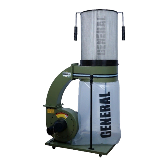
- Page 1 1 1/2 HP Dust Collector #10-105, #10-105CF & 10-105DAS...
-
Page 2: Important Safety Instructions
14. DON’T OVERREACH. Keep proper footing and balance at all times. IMPORTANT SAFETY 15. MAINTAIN TOOLS IN TOP CONDITION. Keep tools sharp INSTRUCTIONS WARNING – To reduce risk of injury: and clean for best and safest performance. Follow instructions for lubricating and changing accessories. 1. -
Page 3: Table Of Contents
Table of Contents IMPORTANT SAFETY INSTRUCTIONS ................... 2 Table of Contents ........................ 3 Electrical Requirements ...................... 4 Specifications ........................5 For Your Own Safety ......................5 Contents of Shipping Carton ....................6 Tools Required for Assembly ....................6 Assembly ..........................7 Operating Instructions ...................... -
Page 4: Electrical Requirements
Electrical Requirements In the event of a malfunction or breakdown, grounding provides a path of least resistance for electric current to reduce the risk of electric shock. This tool is equipped with an electric cord having an equipment-grounding conductor and a grounding plug. The plug must be plugged into a matching outlet that is properly installed and grounded in accordance with all local codes and ordinances. -
Page 5: Specifications
110. Check for damaged parts before/after use. The above specifications were current at the time this manual was published, but because of our policy of continuous improvement, General reserves the right to change specifications at any time and without prior notice, without incurring obligations. -
Page 6: Contents Of Shipping Carton
Contents of Shipping Carton 1 Drum 1 Collection Body and Motor Assembly 1 Canister Filter (CF Model ONLY) 1 “Snap Ring” 1 Belt Clamp 3 Vertical Support Rods 4 Casters 1 Bag Hanger 1 “Y” Fitting Inlet with End Cap 1 5”... -
Page 7: Assembly
ASSEMBLY INSTRUCTIONS • SERIOUS PERSONAL INJURY COULD OCCUR IF YOU CONNECT THE MACHINE TO THE POWER SOURCE BEFORE YOUR HAVE Fig.1 COMPLETED THE SET UP PROCESS. DO NOT HOOK-UP THE MACHINE TO A POWER SOURCE UNTIL INSTRUCTED TO DO SO. •... - Page 8 Fig. 5 6. Attach & Tighten 2 support rods, to base, using 2 hex bolts for each rod. (Fig. 5) 7. With the help of an assistant, line up the holes in the drum assembly with the holes in the support rods and Fig.
- Page 9 Filter Bag Assembly If you purchased a 10-105 Dust Collector, this section Fig. 9 describes the assembly and installation of the contents of the Filter Bag Kit. Filter Bag Installation 1. Attach bag hanger to backside of drum by removing 2 hex nuts that connect the support rods to the drum and slide bag hanger bracket in Fig.
-
Page 10: Operating Instructions
Failure to comply may result in serious injury! The #10-105/#10-105CF dust collectors are rated at 110/220V, Prewired 110V. Use a plug and outlet rated at least 20 amps. The circuit for the machine should also be protected by a minimum 20 amp circuit breaker or fuse. -
Page 11: Changing Bag/Filters
Dryer vent hose is not acceptable for this purpose. Contact your nearest Grounding the Dust Collection System General distributor for the full line of General Dust Collector Hoses and Accessories. Customize your installation and obtain maximum performance The dust collection system includes the dust collector and the hose, with General dust hoods, hoses, clamps, fittings, and blast gates. -
Page 12: Recommended Accessories
“letter of claim” must be included (a warranty claim form can also be used and can be obtained, upon request, from General™ or an authorized distributor) clearly stating the model and serial number of the unit (if applicable) and including an explanation of the complaint or presumed defect in material or workmanship. -
Page 13: Warranty And Service
Electrical diagram for DAS units. -
Page 14: Parts Breakdown For The 1 1/2 Hp Dust Collector With And Without Canister
Schematic for #10-105 Dust Collector... -
Page 15: 1/2 Hp Dust Collector Parts List
Parts Breakdown for #10-105 PART NO. DESCRIPTION SPECIFCATIONS 10105-01 CASTER 10105-02 HEX.HEAD BOLT 5/16"×1/2"L 10105-04A BASE PLATE 10105-05 PAN HEAD SCREW 3/16"×3/8"L 10105-06A INLET COVER 10105-07A CAP SCREW M6×16MM L 10105-09 WASHER 10105-10A 10105-11A COLLECTOR BODY 10105-12 WASHER 5/16" 10105-13 PAN HEAD SCREW 3/16"×3/8"L... - Page 16 10105-46 ON/OFF switch with automatic function 10105-47 switch box B 10105-48 fastener...
Need help?
Do you have a question about the 10-105 and is the answer not in the manual?
Questions and answers