Advertisement
Quick Links
SETUP & OPERATION MANUAL
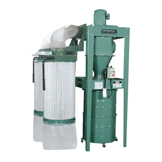
FEATURES
Heavy-duty construction.
Simple design with easy set-up and mainte-
nance.
High quality motor designed specifically for
heavy-duty use and long service life.
Cast steel, high efficiency fan for superior perfor-
mance and low noise level.
Equipped with two ultra efficient 1 micron can-
ister filters to reduce airborne dust and offers
filtering capacity 6 times more than traditional
filter bags.
Canister filter equipped with crank handle/
internal shaker for easy filter cleaning without
removing bag.
2 piece caster mounted 45 gallon (55 U.S. gallon)
drum included (item #10-820B).
SPECIFICATIONS
• Airflow capacity
3800 cfm (10-850CF) / 4955 cfm (10-875CF)
• Air speed
48 m/sec (10-850CF) / 45 m/sec (10-875CF)
• Sound rating
85-90 dB (10-850CF) / 90-95 dB (10-875CF)
• Inlet Diameter (1)
(1) 9" (229 mm) (ou 4) 5" (127 mm) (10-850CF)
(1) 10" (254 mm) (ou 4) 5" (127 mm) (10-875CF)
• Static Pressure
15 5/8" of water (10-850CF) / 16 1/2" (10-875CF)
• Canister Filters (Dia. x H)
20" x 44" x 2 pcs (510 x 1120 mm x 2 pcs)
• Motor
M1 5 HP , 220 V, 1 Ph, 21 A (10-850CF)
M2 5 HP , 220 V, 3 Ph, 13.7 A (10-850CF)
M2 7 1/2 HP , 220 V, 3 Ph, 21.5 A (10-875CF)
M3 5 HP , 600 V, 3 Ph, 4.9 A (10-850CF)
M3 7 1/2 HP , 600 V, 3 Ph, 6.9 A (10-875CF)
• Overall dimensions (L X W X H)
63" x 51" x 90 1/2"
(1600 x 1300 x 2300 mm) (10-850CF)
69" x 59" x 110"
(1750 x 1500 x 2800 mm) (10-875CF)
• Weight
418 LBS (190 kg) with filters (10-850CF)
462 LBS (210 kg) with filters (10-875CF)
10-850CF Version 2/Revision 1 - June 2014 (S/N 14559311)
10-875CF Version 2/Revision 1 - June 2014 (S/N 14697012)
© Copyright General International
2 STAGE DUST COLLECTOR
MODEL
#10-850CF
#10-875CF
Advertisement

Related Manuals for General 10-850CF


Summary of Contents for General 10-850CF
- Page 1 20” x 44” x 2 pcs (510 x 1120 mm x 2 pcs) • Motor M1 5 HP , 220 V, 1 Ph, 21 A (10-850CF) M2 5 HP , 220 V, 3 Ph, 13.7 A (10-850CF) M2 7 1/2 HP , 220 V, 3 Ph, 21.5 A (10-875CF) M3 5 HP , 600 V, 3 Ph, 4.9 A (10-850CF)
-
Page 2: General Safety Rules
1. General safety rules "WARNING When using electric tools basic safety precautions should always be followed to reduce the risk of fire, electric shock and personal injury, including the following. Read all these instructions before attempting to operate this product and save these instructions". -
Page 3: Unpacking And Assembly
If you have any questions relative to a particular application, DO NOT use the machine until you have first contacted GENERAL INTERNATIONAL to determine if it can or should be performed on the product. -
Page 4: Handling And Transportation
<4> Contact local agent for any problem of assembly and missing part. Warning! Do not connect the dust collector to the power source until machine is completely assembled and you have read and understand the entire instruction manual. 4. Handling and transportation The net weight of this machine is about 270 kgs. -
Page 5: Parts List
7. Assembly drawing & instructions Remove the dust collector components from the shipping containers. Please check parts list for missing or damaged parts. 10-850CFM PARTS LIST 1. CARTRIDGE FILTER 2 pieces 14. Ø 8” X 2 OUTLET 1 piece 2. DRUM 1 piece 15. - Page 6 10-875CFM PARTS LIST 2 pieces 1. CARTRIDGE FILTER 2 pieces 16. BAG CLAMP 4 pieces 2. Ø 8” FLEXIBLE HOSE 2 pieces 17. PLASTIC BAG 3 pieces 3. Ø 8” HOSE CLAMP 4 pieces 18. HARDWARE PACKAGE 1 piece 4. Ø 7” HOSE CLAMP 4 pieces 19.
- Page 7 1. Fasten air flow pipe to 3. Fasten drum to blower housing 2. Put the rubber gasket blower housing with four with nine 5/16” flat washer and material around the outer 5/16” flat washer and four nine 5/16” x 3/4 inch-long edge of drum and continue 5/16”...
- Page 8 7. Assemble one leg section to 10. Place one support bracket 8. Assemble remaining three blower housing and fasten on the inside of two upper legs to blower housing in the with four 3/8" x 1 inch-long legs. same manner. screw, four 3/8"...
- Page 9 14. Attach the remaining 15. Put the rubber gasket 16. Attach the outlet port and brackets and lower legs to material around the outer L-type hanger (left) to the upper legs assemblies in edge of ø 8” outlet and blower housing, as shown, the same manner.
- Page 10 20. Connect the two flexible 21. Connect the handle to the 22. Fit the plastic collection bags hose 8” to the outlet / inlet port center of cartridge filter and over the bottom of the cartridge and secure in place with the secure in place with the filter and clamp in place with the 8”...
- Page 11 26.Attach the casters to the 27.Install the three drum 28.Connect the upper and bottom of the lower collection latches,with six 10-24 lower collection drums and drum,using four 3/8” 16 hex 3/8”Phillips head screws and secure with the included nuts,eight 3/8” flat washers, six 10-24 hex nuts.use the metel clamp and bolt.
- Page 12 33.Assemble the 1” 1700 34.Connect the lower collection 32.Before assembling the flexible hose with the drum assemblies to the flexible hose ensure that the 1”clamps.(10-850CFM) vacuum tube. (10-850CFM) 1” plugs are removed from Assemble the two 1” 1700 the vacuum tube and drum flexible hose with the 1”clamps.(10-875CFM) 35.
- Page 13 Identification: 10-850CFM 10-875CFM...
- Page 14 ASSEMBLY DRAWING 10-850CFM 3122/17/41...
- Page 15 REPLACEMENT PARTS LIST 10-850CFM QBSU!OBNF! R(UZ! QBSU!OBNF! R(UZ! 2! NPUPS! 56! VQQFS!MFH! 3! QPXFS!DPSE! 57! MPXFS!MFH! 4! 203#!IFY!OVU! 58! 6027#y!2#!IFY!IE!TDSFX! 5! 203#!GMBU!XBTIFS! 59! 6027#!GMBU!XBTIFS! 6! NPUPS!HBTLFU! 5:! 6027#!MPDL!OVU! 7! NPUPS!CBTF! 61! PVUMFU! 7B! 203#y2.203#!IFY!IE!TDSFX! 62! IBOHFS!)SJHIU*! 7C! 203#!XBTIFS!! 63! IBOHFS!)MFGU*! 8! 6027#y405#!IFY!IE!TDSFX! 64! 6027#!GMBU!XBTIFS! 9! 6027#!GMBU!XBTIFS!
- Page 16 OP! QBSU!OBNF! R(UZ! OP! QBSU!OBNF! R(UZ! 98! 6027#!IFY!OVU! 216C! 205#!GMBU!XBTIFS! 99! DPWFS!DMBNQ! 217! TXJWFM!IBOEMF! 9:! 4027#y!409#!SPVOE!IE!TDSFX! 217B! 6027#y405#!IFY!TDSFX! :1! 4027#!IFY!OVU! 217C! 6027#!TQFDJBM!GMBU!XBTIFS! :2! 4027#y!409#!SPVOE!IE!TDSFX! 218! CFBSJOH! :3! 205#!IFY!OVU! 218B! HSFBTF!TFBM! :4! 3#DBTUFS! 218C! 205#y2#!IFY!IE!TDSFX! :5! 409#!IFY!OVU! 218D! 205#!GMBU!XBTIFS! :6! 409#!MPDL!XBTIFS! 219! TXJWFM!BYJT! :7! 409#!GMBU!XBTIFS! 219B! 205#y!609#M!IFY!IE!TDSFX!
- Page 17 ASSEMBLY DRAWING 10-875CFM 3122/18/16...
- Page 18 REPLACEMENT PARTS LIST 10-875CFM QBSU!OBNF! R(UZ! OP! QBSU!OBNF! R(UZ! 2! NPUPS! 42! 409#!IFY!OVU! 3! QPXFS!DPSE! 43! 409#yPE34y3u!GMBU!XBTIFS! 4! 203#!IFY!OVU! 44! JOMFU!HBTLFU! 5! 203#!GMBU!XBTIFS! 45! JOMFU! 5B! 203#!TQSJOH!XBTIFS! 46! 409#yPE34y3u!GMBU!XBTIFS! 6! NPUPS!HBTLFU! 47! 409#y2#!IFY!TDSFX! 7! 409#!TQSJOH!XBTIFS! 48! 8#!IPTF!DMBNQ! 8! 409#y2.205#!IFY!IE!TDSFX! 49! 8#!GMFYJCMF!IPTF! 9! 409#!IFY!OVU!! 55! DPWFS! :! 409#!GMBU!XBTIFS!
- Page 19 QBSU!OBNF! R(UZ! OP! QBSU!OBNF! R(UZ! 94! DBCMF!HMBOE! 229! 409#!IFY!OVU! 95! 409#y2#!IFY!TDSFX! 22:! 409#!TQSJOH!XBTIFS! 96! 409#yPE34y3u!GMBU!XBTIFS! 231! 409#yPE34y3u!GMBU!XBTIFS! BDSZMJD! 97! DPWFS!DMBNQ! 232! 98! TXJUDI!CBTF! 233! SVCCFSU!IBOEMF! 99! 409#yPE34y3u!GMBU!XBTIFS! 234! 6027#y405#!IFY!TDSFX!! 9:! 409#!IFY!OVU! 235! 6027#ØPE29Ø3u!GMBU!XBTIFS!! :1! TVQQPSU!CSBDLFU!)M*! 236! 6027#!IFY!OVU! :2! TVQQPSU!CSBDLFU!)T*! 237! 203#!TQFDJBM!GMBU!XBTIFS! 3#!IPTF!DMBNQ! 238! 203#y2.203#!IFY!TDSFX! 2#!IPTF!DMBNQ!
Need help?
Do you have a question about the 10-850CF and is the answer not in the manual?
Questions and answers