Table of Contents
Advertisement
Quick Links
Document ID
MANUAL-477767835-1
Date:
November 2020
This confidential document was prepared by the staff of Valeport Limited, the Company, and is the
property of the Company, which also owns the copyright therein. All rights conferred by the law of
the copyright and by virtue of international copyright conventions are reserved to the Company.
This document must not be copied, reprinted or reproduced in any material form, either wholly or in
part, and the contents of this document, and any method or technique available there from, must
not be disclosed to any other person whatsoever without the prior written consent of the Company.
© 2020 Valeport Ltd
Valeport Ltd
St Peter's Quay
Totnes TQ9 5EW
United Kingdom
As part of our policy of continuous development, we reserve the right to alter, without prior notice,
all specifications, designs, prices and conditions of supply for all our equipment
VRS20 Radar Level Gauge
Operating Manual
Phone:
+44 1803 869292
email:
sales@valeportwater.co.uk
Web:
www.valeportwater.co.uk
Advertisement
Table of Contents

Subscribe to Our Youtube Channel
Related Manuals for Valeport VRS20


Summary of Contents for Valeport VRS20
- Page 1 Date: November 2020 This confidential document was prepared by the staff of Valeport Limited, the Company, and is the property of the Company, which also owns the copyright therein. All rights conferred by the law of the copyright and by virtue of international copyright conventions are reserved to the Company.
-
Page 2: Table Of Contents
Setup Commands ......................18 Sampling Commands ..................... 19 Wiring Information ........................ 20 Tidemaster ........................20 Stand Alone ........................21 Declarations of Conformity ....................22 Approvals ........................22 EU Declaration of Conformity ..................23 © 2020 – Valeport Ltd Page | b... -
Page 3: Introduction
VRS20 Radar level gauge 1.1 Description The VRS-20 is a pulsed k-band radar level sensor developed by Valeport to work seamlessly with Valeport's TideMaster and TideStations. VRS-20 can be operated in a standalone mode, with optional telemetry systems or interfaced directly to a third party data logger or PC. -
Page 4: Installation
1 to 2.5mm flat bladed screwdriver – to release the terminal clamps Junction Box 19mm A/F Spanner – to close the cable glands 5 to 6mm flat bladed screwdriver – for the fasteners in the junction box lid © 2020 – Valeport Ltd Page | 2... - Page 5 VRS20 Radar Level Gauge: MANUAL-477767835-1 | issue: 5.0 © 2020 – Valeport Ltd Page | 3...
-
Page 6: Mounting On A Boom
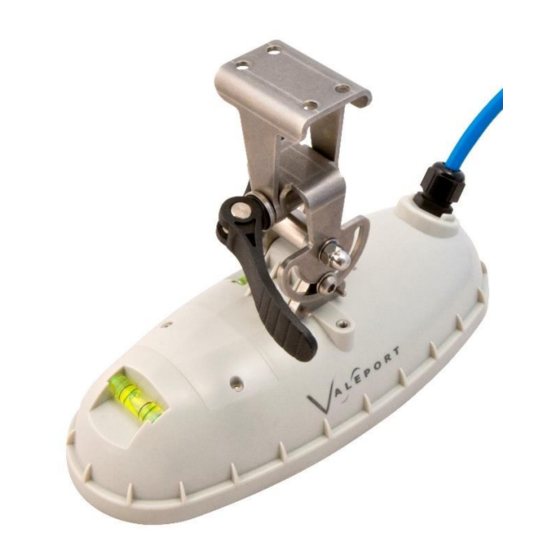
Installation 2.2 Mounting on a Boom The radar is supplied with a stainless-steel clamp (as pictured) for attaching to railings/scaffold poles. Constructed from standard scaffolding parts and attached to existing railing structure: © 2020 – Valeport Ltd Page | 4... -
Page 7: Direct Mounting
VRS20 Radar Level Gauge: MANUAL-477767835-1 | issue: 5.0 2.3 Direct Mounting The clamp can be removed and the stainless-steel adaptor plate fitted directly to a mounting surface if required. The diagram below gives the dimensions of the adaptor plate in millimetres. -
Page 8: Wiring
To insert the bare wires into the terminals, push in the orange tab in with a fine screwdriver and release to clamp the wire. Check the wire is securely clamped by pulling gently on the wire. The output from the junction box will depend on the configuration of the VRS-20. © 2020 – Valeport Ltd Page | 6... -
Page 9: Communications
VRS-20 instructions. 3.1 RS232 Communications Direct communication with a standalone VRS-20 is via a terminal program such as Valeport Terminal or HyperTerminal. Details of the commands that can be manually sent and received are provided in the # Codes section. -
Page 10: Sdi12 Communications
SDI-12 verifier from NR Systems, Inc. There is no functionality via the SDI-12 interface to change VRS20 configuration so any configuration changes such as output units, sampling period or datum offsets must be made via the serial interface. - Page 11 - the number of measurement values the sensor will make and return in one or more subsequent D commands; For the VRS20 n= 5 and value will return in positions D0 to D4 If using this command the response to aD0! command is...
-
Page 12: Data
$PVRS0,07,4.225,2.206,0.009,000,m*75 $PVRS0,07,4.219,2.212,0.013,000,m*75 $PVRS0,07,4.211,2.220,0.010,000,m*70 $PVRS0,07,4.197,2.234,0.009,000,m*71 $PVRS0,07,4.191,2.240,0.007,000,m*79 4.2 Data Status An error code status of 000 is no reported errors. Any error code outside of this list should be reported to Valeport Support support@valeport.co.uk © 2020 – Valeport Ltd Page | 10... -
Page 13: Sampling Modes
When paired with a TideMaster the radar sampling pattern is chosen from a series of predefined modes. The measurement and timing is controlled by the TideMaster logger The VRS20 is turned off between measurements to conserve power. Burst sampling pattern of 30 seconds / 1 minute... -
Page 14: Stand Alone Operation
(3600s) and the maximum measurement duration is 6 minutes (360s). The VRS20 does not have a low power sleep mode in the idle time between measurements. If power conservation is critical then the VRS20 will need to be turned off between measurement cycles by the controlling system. -
Page 15: Operational Sequence
VRS20 Radar Level Gauge: MANUAL-477767835-1 | issue: 5.0 Function Command Options: Set Measurement Duration #128;nnn nnn = duration of 1Hz measurements. Maximum Value = 360 Report Measurement Duration #129 Set measurement interval in seconds. #204;xxx xxx = Interval between measurement reports... -
Page 16: Single Mode
Run single sampling NN:Sxxx NN = RS485 address measure xxx = measurement duration NB. This does not include pre-amble time Reports last NN:L Only works in conjunction with Single mode recorded reading © 2020 – Valeport Ltd Page | 14... -
Page 17: Continuous Mode
In addition to the simple averaging and outlier rejection carried out over a sampling period, exponential and running mean filters can be enabled to smooth the output of the VRS20. A filter time constant controls the amount of smoothing applied and how long the radar takes to recognise a step change. - Page 18 Sampling modes © 2020 – Valeport Ltd Page | 16...
- Page 19 VRS20 Radar Level Gauge: MANUAL-477767835-1 | issue: 5.0 Function Command Options: Sets Filtering algorithm #224;x Where 0 = no filtering (default) 1 = Exponential 2 = Running Mean Reports Filtering algorithm #225 Sets Filtering Time constant #222;xxx Where xxx = filter time constant in seconds.
-
Page 20: Codes
X Set output units for range +height. 0 = Units in Metres 1 = Units in Feet Y Set time/date placeholder. 0 = No time/date 1 = Add time/date Report Output Units #091 © 2020 – Valeport Ltd Page | 18... -
Page 21: Sampling Commands
VRS20 Radar Level Gauge: MANUAL-477767835-1 | issue: 5.0 Function Command Notes: Set Datum Offset Value #092;x.xxx Sets offset value in currently configured units for transformation from Range to Height above Datum. NB datum value is reset to 20m or 65ft... -
Page 22: Wiring Information
POWER_GND 6Way plug POWER_IN Terminal UTS6JC10E6P block RS232_OUT OF (Stripped & RADAR twisted end) RS232_IN TO RADAR RS232_GND SCREEN 9Way D-Type RS232_OUT OF Plug RADAR RS232_IN TO RADAR 1,5,6,8, RS232_GND SHELL SCREEN © 2020 – Valeport Ltd Page | 20... -
Page 23: Stand Alone
VRS20 Radar Level Gauge: MANUAL-477767835-1 | issue: 5.0 7.2 Stand Alone END 1: END 2: END 3: FROM RADAR INTO OUT OF JUNCTION BOX D-TYPE JUNCTION BOX CONNECTOR BOARD CONNECTOR PIN CONNECTOR PIN FUNCTION POWER_GND 6Way Terminal POWER_IN block Plug... -
Page 24: Declarations Of Conformity
Declarations of Conformity 8 Declarations of Conformity 8.1 Approvals The VRS20 radar sensor is fully compliant with: ETSI EN 302 729-2 V1.1.2(2011-05) Electromagnetic compatibility and Radio spectrum Matters (ERM); Short Range Devices (SRD); Level Probing Radar (LPR) equipment operating in the frequency ranges 6 GHz to 8,5 GHz, 24,05 GHz to 26,5 GHz, 57 GHz to 64 GHz, 75 GHz to 85 GHz;... -
Page 25: Eu Declaration Of Conformity
Please note: Any changes or modifications to the product or accessories supplied, that are not authorised by Valeport Ltd, could void the CE compliance of the product and negate your authority to operate it. This product has demonstrated CE compliance under conditions that include the use of shielded cables. - Page 26 Declarations of Conformity © 2020 – Valeport Ltd Page | 24...
- Page 27 VRS20 Radar Level Gauge: MANUAL-477767835-1 | issue: 5.0 © 2020 – Valeport Ltd Page | 25...
Need help?
Do you have a question about the VRS20 and is the answer not in the manual?
Questions and answers