Table of Contents
Advertisement
Document Ref:
06508141a
Date:
09 March 2017
This document was prepared by the staff of Valeport Limited, the Company, and is the property of
the Company, which also owns the copyright therein. All rights conferred by the law of the
copyright and by virtue of international copyright conventions are reserved to the Company. This
document must not be copied, reprinted or reproduced in any material form, either wholly or in
part, and the contents of this document, and any method or technique available therefrom, must
not be disclosed to any other person whatsoever without the prior written consent of the
Company.
Valeport Limited
St Peters Quay
Totnes
Devon, TQ9 5EW
United Kingdom
As part of our policy of continuous development, we reserve the right to alter, without prior notice,
all specifications, designs, prices and conditions of supply for all our equipment.
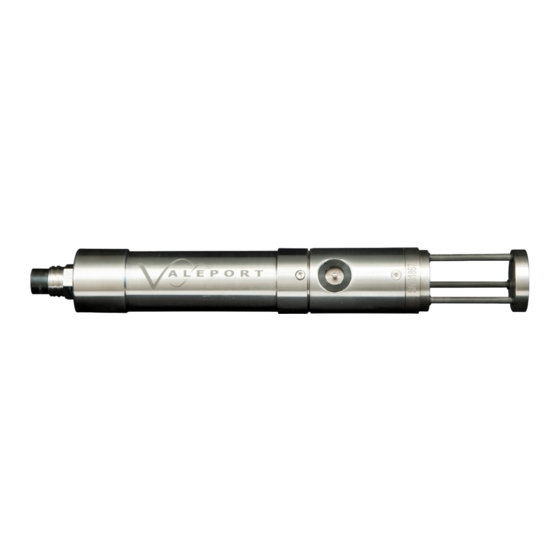
miniSVS
Operating Manual
Tel:
+44 1803 869292
e mail:
sales@valeport.co.uk
Web:
www.valeport.co.uk
Advertisement
Table of Contents

Related Manuals for Valeport miniSVS


Summary of Contents for Valeport miniSVS
- Page 1 Date: 09 March 2017 This document was prepared by the staff of Valeport Limited, the Company, and is the property of the Company, which also owns the copyright therein. All rights conferred by the law of the copyright and by virtue of international copyright conventions are reserved to the Company. This...
-
Page 2: Table Of Contents
Table of Contents Page 2 Page 2 Table of Contents 1. Introduction ............................. 3 2. Sensors ............................. 4 2.1. Specifications ............................ 4 2.2. Physical Characteristics ............................ 5 3. Communications ............................. 7 3.1. Sampling Modes ............................ 7 3.2. Data Formats ............................ 7 3.3. -
Page 3: Introduction
This configuration is used in the SoundBar 2 Digital Bar Checker, where a 100 dBar range transducer is used, but the miniSVS may be fitted with a selection of different range transducers up to 6000 dBar. The pressure option also uses a secondary PCB. -
Page 4: Sensors
2.1.1. Power · Requires 8 – 29V DC input · miniSVS draws approximately 17mA at 12V DC · miniSVS with pressure draws approximately 24mA at 12V DC · miniSVS with temperature draws approximately 20mA at 12V DC 2.1.2. Data Output Units are fitted with both RS232 and RS485 communications as standard. -
Page 5: Physical Characteristics
SV Transducer Ceramic transducer behind polycarbonate window. Signal cable 3mm co-ax cable, nominal 25cm length. Push fit connector. Pressure Transducer Stainless steel diaphragm with acetal protective cover. Temperature sensor PRT in titanium housing with polyurethane backing. © 2017 Valeport Ltd... - Page 6 Page 6 2.2.1. Dimensions Dependent on type supplied. See diagram below © 2017 Valeport Ltd...
-
Page 7: Communications
M60<enter> Unit free runs at 60Hz 3.2. Data Formats Data output is dependent on the parameters fitted to the miniSVS and the output format selected. Pressure data format is dependent on sensor range, and may be any of the following. - Page 8 Page 8 3.2.1. Valeport Standard Format #082;off Sets data format to standard Valeport mode (SV in mm/s) SV only <space>1234567<cr><lf> where 1234567 is the speed of sound in mm/sec[i.e. 1234.567 m/sec] P + SV <space>{pressure}<space>1234567<cr><lf> where 1234567 is the speed of sound in mm/sec[i.e. 1234.567 m/sec] T + SV <space>{temperature}<space>1234567<cr><lf>...
- Page 9 SSSS.SSSS is salinity value VVVVV.VVV is sound velocity in m/s In this format, the miniSVS will substitute zeroes for parameters it cannot measure. 3.2.5. Seabird CTD format #082;SEABIRD Sets the miniSVS to output in Seabird CTD mimic mode TTT.TTTT,CC.CCCCC,PPPPP.PPPP, SSSS.SSSS,VVVVV.VVV <cr><lf>...
- Page 10 Where pppp.p denotes pressure/depth ssss.ss denotes speed of sound tt.ttt denotes temperature In this format, the miniSVS will substitute zeroes for parameters it cannot measure. 3.2.8. Sonardyne Format for use with Compatt #013;on Sets the unit to Sonardyne format #013;off Returns the unit to normal operation ©...
-
Page 11: Wiring Information
Internal Co-axial connector to sensor (J3) 5 – way FCI (power and comms) (J1) NB: J2 & J4 are for Valeport calibration and setup purposes – not for use by customer. External Standard is SubConn type MCBH6F (In titanium on titanium housings, in... - Page 12 5 (Link to 6,8,9) RS232 Tx (Out of sensor) or White RS485A RS232 Rx (Into sensor) or RS485B Green Link to Pin 1 for RS485 Orange N/C for RS232 6 (Link to pin Blue Power GND 1 in sensor) © 2017 Valeport Ltd...
- Page 13 Yellow RS485A White Power & RS232 Ground 9 – 28V DC input RS232 Tx (out of sensor) Brown RS485B Link to Pin 2 for RS485. Orange N/C for RS232 Blue Screen Note: Do not connect screen. © 2017 Valeport Ltd...
- Page 14 Systems are supplied with a free end lead for splicing Impulse MHDG-5-BCR Free End Function Wire Colour Wire Screen Green RS232 Ground White / Black RS232 TX (out of sensor) White / Red RS232 RX (in to sensor) Black -V (join to pin 1) © 2017 Valeport Ltd...
- Page 15 Communications Page 15 3.3.5. Housed Systems (SubConn OM8F connector, optional fit only) SVS Test Cable, 3m Valeport 8-Core Cable. SubConn 8 pin 9 Way D male line (OM8F + 4mm Banana Plugs Type Function OMBB) Wire colour Red Plug Black Plug...
- Page 16 3.3.6. MVP Housed Systems (SubConn Male Bulkhead Connector) miniSVS instruments built to operate with MVP equipment can be operated in RS232 or RS485 serial comms modes. In order to operate in RS485 pins 2 to 5 have to be linked. This can be done as a factory build setting and are designated 'Internal' RS485 configuration or as an optional setting externally to the instrument.
- Page 17 Link to 5* *or in the mating SubConn link pin 2 to pin 5 Note: RS485 A/B is not formally specified. If data cannot be read successfully it may be that the RS485A/B need to be swapped © 2017 Valeport Ltd...
-
Page 18: Operations
Turns Tare mode off (i.e. unit outputs pressure as read) #009; Unit takes single pressure reading to use as Tare value. #009;0 Sets Tare value to zero (i.e. removes tare) #009; Input Tare value in units of 0.001dBar (i.e. 9000 = 9dBar) {value} © 2017 Valeport Ltd... -
Page 19: Other Commands
Sets RS485 address (01 to 99) #005;ON or OFF Turns Address mode ON or OFF #006 Returns ON or OFF for address mode #026;{xxxx} Sets data separator for Valeport mode. Default is <space>, separator may be up to 4 characters. © 2017 Valeport Ltd... -
Page 20: Appendix 1: Faq's
5. Appendix 1: FAQ’s Why is the Data Different From My Old CTD Data? Quite simply, the Valeport SV sensor is more accurate than anything else that has previously been available. The CTD formulae (Chen & Millero, Del Grosso etc.) all have errors in them –... - Page 21 This will normally wash off during the up-cast. It can also happen if the sensor has been deployed for some time without cleaning, and there is significant growth on the sensor. © 2017 Valeport Ltd...
Need help?
Do you have a question about the miniSVS and is the answer not in the manual?
Questions and answers