Advertisement
Quick Links
TROUBLE SHOOTING
The door will not open and
The sensor power is off.
LED does not light up.
The door will not open and
The wiring of relay output is
not connected correctly.
LED lights up.
The door opens when
The mode of relay output is
no detection occurs and
incorrect.
closes during detection.
The cut of the masking lens is
The detection fi eld is
wrong. The sensor is installed in
abnormal
wrong position or angle.
The environment is complicated,
Error detection happens
and has strong interfering
frequently.
resource.
Accessories
+
MINI FLY
+
Cable 2.5m/4m (optional)
+
MINI FLY
* MBKT need separate order.
SAFETY INSTRUCTIONS
The manufacturer of the door system is responsible for carrying out a risk assessment and installing the sensor and the door system
in compliance with applicable national and international regulations and standards on door safety.
Only trained and qualifi ed personnel may install and setup the sensor.
The warranty is void if unauthorized repairs are made or attempted by unauthorized personnel.
Avoid touching any electronic and optical components.
BEA | 3rd-5th Floor Tower B / No.10 Jiu Xian Qiao North Road, Chao yang District, Beijing | T +86 10 57761616 / F +86 10 62628775 | INFO@BEA.BE |
Angleur, November 2010
Jean-Pierre Valkenberg, Authorized representative
The complete declaration of conformity is available on our website: www.bea.be
Only for EC countries: According to the European Guideline 2002/96/EC for Waste Electrical and Electronic Equipment (WEEE)
MINI FLY
1
Check the wiring and the power supply.
1
Check the relay wiring.
1
Change the position of dip-switch 2.
1
Cut out a new lens to meet the required of sensing fi eld size.
2
Install the sensor in the right way.
1
Setting dip-switch 1 to ON state, as the strong
interference model.
=
MFCA
MINI FLY UP
=
Masking lens
Screw
=
MBKT *
FLY OVER
Other use of the device is outside the permitted purpose and can not be
guaranteed by the manufacturer. The manufacturer cannot be held responsible for
incorrect installations or inappropriate adjustments of the sensor.
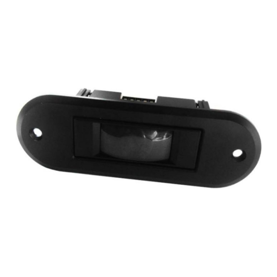
DESCRIPTION
3
4
1
2
1
1.
Cover
Cover
2.
Lens
3.
LED
4.
Passive infrared sensor
TECHNICAL SPECIFICATIONS
Features:
Microprocessor control/ temperature compensation technology/ adjustable installed angle
Mounting height:
Up to 3.5m
Mounting angles:
-4° to +4°
Maximum detection area :
2.5m (W) ×1.5m (D) mounting height of 2.2m
4.0m (W) ×2.4m (D) mounting height of 3.5m
Detection mode:
Movement
Detection speed:
0.1 to 1.5m/s
Relay hold time:
0.5s/2s
Max 200 ms
Response time:
12 VDC -10% to 24 VDC+30% /
Power supply:
12 VAC to 24 V AC +/-10 %
50/60 Hz
Main frequency:
Power consumption:
<1W
Temperature range:
-30°C to +55°C
Degree of protection:
IP54
Standard output relay:
Max contact voltage
60 V DC/ 42 V AC
1A (resistive)
Max contact current
Max switching power
30W (DC) / 60 VA(AC)
Immunity:
Electromagnetic compatibility(EMC) according to 89/336/EEC
Dimensions of sensor:
64mm(W)×41mm(H)×23mm(D)
MINI FLY
The most advanced technology in passive
infrared sensor range
5
6
7
5
5.
U
Unplug 5-wire connector
6.
Dip-switch
7.
Potentiometer
Specifi cations are subject to changes without prior notice.
All values measured in optimal conditions.
Advertisement

Related Manuals for BEA MINI FLY


Summary of Contents for BEA MINI FLY
- Page 1 Max contact voltage 60 V DC/ 42 V AC BEA | 3rd-5th Floor Tower B / No.10 Jiu Xian Qiao North Road, Chao yang District, Beijing | T +86 10 57761616 / F +86 10 62628775 | INFO@BEA.BE | 1A (resistive)
- Page 2 Mounting tips: Adjustment the sensitivity with potentiometer The sensor must be fi rmly fastened in order to avoiad vibrations. When mounting the MINI FLY, make sure you adjusting the angle LED: before tightening the screws. When sensor is power on , it fl ash10 seconds.
Need help?
Do you have a question about the MINI FLY and is the answer not in the manual?
Questions and answers