Advertisement
Quick Links
DESCRIPTION
1
1. faceplate
2. mounting ring
3. set screws
4. backplate
TECHNICAL SPECIFICATIONS *
Technology
Detection Mode
Supply Voltage
Current Consumption
Temperature Range
Enclosure Rating
Sensing Zone **
Relay
Dimensions (Overall)
Wire Harness Length ***
Material
** Sensing Zone is dependent upon
•
Size (area) of object
•
Orientation of object
•
Speed of object
•
Environmental conditions
*** 5 conduct wire needed between sensor and door control
* Use of the device outside the intended application cannot be guaranteed by the manufacturer.
75.5737.10 MS-21H 20150617
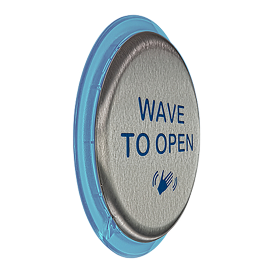
MAGIC SWITCH: MS21H
Hardwired | Stainless Steel | Touchless |
Activation Sensor*
6'' Round (shown)
Text & Logo - 10MS21HR1
Logo - 10MS21HRLL
Text - 10MS21HR
2
5
6
3
Capacitive Sensing
Proximity
12-24 VAC/DC
37 mA (typical)
-20°F to +120°F
NEMA 4
Maximum sensing zone of up to four (4) inches
1-Form A Solid State Relay
0.4A 60VAC/VDC (max)
6'' round - 7'' (DIA) x 0.5'' (D)
4.75'' square - 5.75'' (H) x 5.75'' (W) x 0.5'' (D)
6 inches (5 conductor)
Stainless Steel (faceplate)
Clear Polycarbonate (mounting ring, backlplate, enclosure)
4.75'' Square
Text & Logo - 10MS21HS1
Logo - 10MS21HSLL
Text - 10MS21HS
5. NEMA 4 enclosure
6. wire harness
7. DIP switches
8. potentiometer
Specifications are subject to change without prior notice.
PATENT PENDING
4
7
8
Page 1 of 4
Advertisement

Subscribe to Our Youtube Channel
Summary of Contents for BEA MS21H
- Page 1 MAGIC SWITCH: MS21H Hardwired | Stainless Steel | Touchless | Activation Sensor* 6’’ Round (shown) 4.75’’ Square Text & Logo - 10MS21HR1 Text & Logo - 10MS21HS1 Logo - 10MS21HRLL Logo - 10MS21HSLL Text - 10MS21HR Text - 10MS21HS PATENT PENDING DESCRIPTION 1.
- Page 2 PRECAUTIONS The door control unit Only trained and Always test the proper The warranty is invalid if and the door cover qualified personnel operation of the unauthorized repairs are profile must be correctly may install and setup installation before made or attempted by grounded.
- Page 3 WIRING IMPORTANT WIRING NOTES: Be sure to always use the BEA provided isolation module. * If using a shielded wire harness, both ends of the shielding foil must be connected to Earth Ground. If using a wire harness with more than 5 conductors, all extra conductors must be wired to Earth Ground.
-
Page 4: Troubleshooting
If you are not an AAADM certified inspector, BEA strongly recommends you have an AAADM certified inspector perform an AAADM inspection and place a valid inspection sticker below the safety information label prior to putting the equipment into operation.


Need help?
Do you have a question about the MS21H and is the answer not in the manual?
Questions and answers