
Related Manuals for Baumer Hubner EExOG 9


Summary of Contents for Baumer Hubner EExOG 9
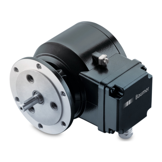
- Page 1 Montage- und Betriebsanleitung Mounting and operating instructions EExOG 9 Inkrementaler Drehgeber mit Ex-Schutzzulassung Incremental encoder with EX approval...
-
Page 2: Table Of Contents
Schritt 2 ................................Schritt 3 ................................Schritt 4 ................................Maximal zulässige Montagefehler unter Verwendung der Baumer Hübner Federscheibenkupplung K 35 ................Hinweis bei Verwendung einer Klauenkupplung (zum Beispiel „ROTEX®“) ....Kabelanschluss - Schritt 1 ........................Kabelanschluss - Schritt 2 ........................ - Page 3 ................................... Step 3 ................................Step 4 ................................Maximum permissible mounting tolerance when the Baumer Hübner K 35 spring disk coupling is used ..............Note when using a jaw-type coupling (for example “ROTEX®”) ........Cable connction - step 1 .......................... Cable connection - step 2 ........................
-
Page 4: Allgemeine Hinweise
Gebrauchte Elektro- und Elektronikgeräte dürfen nicht im Hausmüll entsorgt werden. Das Produkt enthält wertvolle Rohstoffe, die recycelt werden können. Wenn immer möglich sollen Altgeräte lokal am entsprechenden Sammeldepot entsorgt werden. Im Bedarfsfall gibt Baumer den Kunden die Möglichkeit, Baumer-Produkte fachgerecht zu entsor- gen. Weitere Informationen siehe www.baumer.com. Achtung! Beschädigung des auf dem Gerät befindlichen Siegels... -
Page 5: General Notes
Whenever possible, waste electrical and electronic equipment should be disposed locally at the authorized collection point. If necessary, Baumer gives customers the opportunity to dispose of Baumer products profession- ally. For further information see www.baumer.com. -
Page 6: Betrieb In Explosionsgefährdeten Bereichen
Betrieb in explosionsgefährdeten Bereichen Betrieb in explosionsgefährdeten Bereichen Das Gerät entspricht den Anforderungen der Richtlinie 2014/34/EU für explosionsgefährdete Bereiche sowie dem IECEx-Scheme. Der Einsatz ist gemäß der Gerätekategorie 2 G (Ex-Atmosphäre Gas) zulässig. Ex-Kennzeichnung: II 2 G Ex db eb IIC T5/T6 Gb Ex db eb IIC T5/T6 Gb Normenkonformität: EN 60079-0:2012 + A11:2013 / IEC 60079-0:2011 (Ed.6) -
Page 7: Operation In Potentially Explosive Environments
Operation in potentially explosive environments Operation in potentially explosive environments The device complies with the directive 2014/34/EU for potentionally explosive atmospheres and with the IECEx Scheme. It can be used in accordance with equipment category 2 G (explosive gas atmosphere). Ex labeling: II 2 G Ex db eb IIC T5/T6 Gb Ex db eb IIC T5/T6 Gb... -
Page 8: Sicherheitshinweise
Sicherheitshinweise Sicherheitshinweise Verletzungsgefahr durch rotierende Wellen Haare und Kleidungsstücke können von rotierenden Wellen erfasst werden. • Vor allen Arbeiten alle Betriebsspannungen ausschalten und Maschinen stillsetzen. Zerstörungsgefahr durch elektrostatische Aufladung Die elektronischen Bauteile im Gerät sind empfindlich gegen hohe Spannungen. • Steckkontakte und elektronische Komponenten nicht berühren. •... -
Page 9: Security Indications
Security indications Security indications Risk of injury due to rotating shafts Hair and clothes may become tangled in rotating shafts. • Before all work switch off all voltage supplies and ensure machinery is stationary. Risk of destruction due to electrostatic charge Electronic parts contained in the device are sensitive to high voltages. -
Page 10: Vorbereitung
Vorbereitung / Preparation Vorbereitung Preparation Lieferumfang Scope of delivery Option Gehäuse Housing EURO-Flansch B10 EURO flange B10 Vollwelle mit Passfeder Solid shaft with key Klemmenkastendeckel Terminal box cover Kabelverschraubung Cable gland M16x1,5 mm für Kabel ø7...11 mm oder M16x1.5 mm for cable ø7...11 mm M20x1,5 mm für Kabel ø9...14 mm M20x1.5 mm for cable ø9...14 mm Doppelnippel... -
Page 11: Zur Montage Erforderlich (Nicht Im Lieferumfang Enthalten)
Vorbereitung / Preparation Zur Montage erforderlich Required for mounting (nicht im Lieferumfang enthalten) (not included in scope of delivery) Anbauvorrichtung, kundenspezifisch Installation fitting, customized Befestigungsschrauben für Anbauvorrichtung Fixing screws for installation fitting ISO 4017, M6x16 mm ISO 4017, M6x16 mm Federscheibenkupplung K 35, Spring disk coupling K 35, als Zubehör erhältlich, siehe Abschnitt 5.5. -
Page 12: Montage
Montage / Mounting Montage Mounting Schritt 1 Step 1 Anzugsmoment: Tightening torque: = 1 Nm 2.5 mm Schritt 2 Step 2 10 mm * Siehe Seite 8 See page 8 Antriebswelle einfetten. Lubricate drive shaft. Die Antriebswelle sollte einen The drive shaft should have as less möglichst kleinen Rundlauffehler runout as possible because this can aufweisen, da dieser zu einem... -
Page 13: Schritt 3
Montage / Mounting Schritt 3 Step 3 10 mm Schritt 4 Step 4 2.5 mm Anzugsmoment: Tightening torque: = 1.3 ±10 % Nm * Siehe Seite 8 See page 8 MB051T1 - 11102656 Baumer_EEXOG9-T1_II_DE-EN (19A2) -
Page 14: Maximal Zulässige Montagefehler Unter Verwendung Der Baumer Hübner Federscheibenkupplung K 35
Montage / Mounting Maximal zulässige Montagefehler Maximum permissible mounting toler- unter Verwendung der Baumer Hübner ance when the Baumer Hübner K 35 Federscheibenkupplung K 35 spring disk coupling is used Geräte mit Vollwelle sollten unter Verwen- Devices with a solid shaft should be dung der Baumer Hübner Federschei-... -
Page 15: Hinweis Bei Verwendung Einer Klauenkupplung (Zum Beispiel „Rotex®")
Montage / Mounting Hinweis bei Verwendung einer Klauen- Note when using a jaw-type coupling kupplung (zum Beispiel „ROTEX®“) (for example “ROTEX®”) Eine falsche Montage der Klauenkupplung Incorrect mounting of the jaw-type cou- führt zur Beschädigung des Gerätes. pling can damage the device. Mit einem Tiefenmessschieber die Use a depth gauge to find and observe korrekten Abstände (L, L1), siehe unten,... -
Page 16: Kabelanschluss - Schritt 1
Montage / Mounting Kabelanschluss - Schritt 1 Cable connction - step 1 TX 20 20 mm ( 5 * = M16x1.5 mm) 24 mm ( 5 * = M20x1.5 mm) Kabelanschluss - Schritt 2 Cable connection - step 2 ø7...11 mm ( 5 * = M16x1.5 mm) ø9...14 mm ( 5 * = M20x1.5 mm) ≥13 mm ( 5 * = M16x1.5 mm) ≥14 mm ( 5 * = M20x1.5 mm) -
Page 17: Kabelanschluss - Schritt 3 Bis 6
Montage / Mounting Kabelanschluss - Schritt 3 bis 6 Cable connection - step 3 up to 6 Isolierband Kabelschirm Insulating tape Cable shield M16x1.5 mm: ø7...11 mm M20x1.5 mm: ø9...14 mm * Kabelschirmende Cable shield end Markieren wenn der Kabelmantel die Feder berührt. Mark when the cable jacket contact the spring. -
Page 18: Kabelanschluss - Option Mit Erweiterung Von M16 Auf M20
Montage / Mounting 5.10 Kabelanschluss - Option mit Erweite- 5.10 Cable connection - option with exten- rung von M16 auf M20 sion from M16 to M20 5.11 Kabelanschluss - Schritt 7 5.11 Cable connection - step 7 TX 20 Anzugsmoment: Tightening torque: Ansicht X = 2...3 Nm... -
Page 19: Montagehinweis
Montage / Mounting 5.12 Montagehinweis 5.12 Mounting instruction Bitte beachten dass nur ortsfeste Please note that the cable must be Kabelverlegung zulässig ist! mounted fixed! Wir empfehlen, das Gerät so zu It is recommended to mount the device montieren, dass der Kabelanschluss with cable connection facing down- keinem direkten Wassereintritt ward and being not exposed to water. -
Page 20: Abmessungen
Abmessungen / Dimensions Abmessungen Dimensions (73775, 73781) (73775, 73781) Mit Kabelverschraubung M16x1,5 mm With cable gland M16x1.5 mm Drehrichtung positiv Positive rotating direction M16x1.5 Option: Erweiterung auf M20x1,5 Option: Extension to M20x1.5 M20x1.5 Mit Kabelverschraubung M20x1,5 mm With cable gland M20x1.5 mm Drehrichtung positiv Positive rotating direction M20x1.5... -
Page 21: Elektrischer Anschluss
Elektrischer Anschluss / Electrical connection Elektrischer Anschluss Electrical connection Beschreibung der Anschlüsse Terminal significance Betriebsspannung (für das Gerät) +UB; + Voltage supply (for the device) Masseanschluss (für die Signale) ; ; GND; 0V Ground (for the signals) Erdungsanschluss (Gehäuse) Earth ground (housing) Ausgangssignal Kanal 1 K1;... -
Page 22: Klemmenbelegung
(inputs and outputs). Sensorkabel HEK 8 (Zubehör) Sensor cable HEK 8 (accessory) Es wird empfohlen, das Baumer Hübner Baumer Hübner sensor cable HEK 8 is Sensorkabel HEK 8 zu verwenden oder recommended. As a substitute a shielded ersatzweise ein geschirmtes, paarig ver- twisted pair cable should be used. -
Page 23: Demontage
Demontage / Dismounting Demontage Dismounting Schritt 1 und 2 Step 1 and 2 TX 20 20 mm * Siehe Seite 7 oder 8 See page 7 or 8 MB051T1 - 11102656 Baumer_EEXOG9-T1_II_DE-EN (19A2) -
Page 24: Schritt 3
Demontage / Dismounting Schritt 3 Step 3 10 mm 2.5 mm Schritt 4 Step 4 Schritt 5 Step 5 * Siehe Seite 8 2.5 mm See page 8 MB051T1 - 11102656 Baumer_EEXOG9-T1_II_DE-EN (19A2) -
Page 25: Eu-Konformitätserklärung
Signature/nom/fonction Baumer_EExOG9_DE-EN-FR_CoC_81201520.docm/kwe Baumer Hübner GmbH P.O. Box 126943 ∙ D-10609 Berlin ∙ Max-Dohrn-Str. 2+4 ∙ D-10589 Berlin Phone +49 (0)30 69003-0 ∙ Fax +49 (0)30 69003-104 ∙ info@baumerhuebner.com ∙ www.baumer.com Sitz der Gesellschaft / Registered Office: Berlin, Germany ∙ Geschäftsführer / Managing Director: Dr. Oliver Vietze, Dr. Johann Pohany Handelsregister / Commercial Registry: AG Charlottenburg HRB 96409 ∙... -
Page 26: Technische Daten
Technische Daten Technische Daten 10.1 Technische Daten - elektrisch • Betriebsspannung: 9...30 VDC (HTL) 5 VDC ±5 % (TTL) 9...26 VDC (TTL - R) • Betriebsstrom ohne Last: ≤100 mA • Impulse pro Umdrehung: 120...5000 (je nach Bestellung) • Phasenverschiebung: 90°... -
Page 27: Technical Data
Technical data Technical data 10.1 Technical data - electrical ratings • Voltage supply: 9...30 VDC (HTL) 5 VDC ±5 % (TTL) 9...26 VDC (TTL - R) • Consumption w/o load: ≤100 mA • Pulses per revolution: 120...5000 (as ordered) • Phase shift: 90° ±20° •... -
Page 28: Zubehör
• Analyzer for encoders HENQ 1100 HENQ 1100 * Siehe Abschnitt 4 See section 4 Baumer Hübner GmbH Originalsprache der Anleitung ist Deutsch. P.O. Box 12 69 43 · 10609 Berlin, Germany Technische Änderungen vorbehalten. Phone: +49 (0)30/69003-0 · Fax: +49 (0)30/69003-104 Original language of this instruction is German.
Need help?
Do you have a question about the Hubner EExOG 9 and is the answer not in the manual?
Questions and answers