
Related Manuals for Aigis Mechtronics MLA Series

Summary of Contents for Aigis Mechtronics MLA Series
- Page 1 MLA S ERIES UTDOOR OMES Tilt MLA2CH211 MLA2WD211 MLA2DN211 N S T A L L A T I O N A N D P E R A T I N G N S T R U C T I O N S W W W A I G I S M E C H C O M...
-
Page 2: Safety Precautions
SAFETY PRECAUTIONS CAUTION:TO REDUCE THE RISK OF ELECTRICAL SHOCK, DO NOT OPEN COVERS. NO USER SERVICE- ABLE PARTS INSIDE. REFER SERVICING TO QUALIFIED SERVICE PERSONNEL. This label may appear on the bottom of the unit due to space limitations. The lightning flash with an arrowhead symbol within an equilateral triangle is intended to alert the user to the presence of uninsulated "dangerous voltage"... - Page 3 SECURITE DANGER: POUR ÉVITER TOUT RISQUE D'ÉLECTROCUTION, NE PAS OUVRIR LE BOÎTIER. IL N'Y A PAS DE PIÈCES REM- PLAÇABLES À L'INTÉRIEUR. POUR TOUTE RÉVISION, S'ADRESSER À UN TECHNICIEN SPÉCIALISÉ. En raison de limitation de place, cette étiquette peut être placée sur le dessous de l'appareil.
- Page 4 SICHERHEITSVORKEHRUNGEN VORSICHT: UM EINEN ELEKTRISCHEN SCHLAG ZU VERMEI- DEN, ABDECKUNG NICHT ENTFERNEN.WARTUNGEN ALLER ART QUALIFIZIERTEM PERSONAL ÜBERLASSEN. Aus Platzgründen kann diese Warnung auf der Unterseite des Gerätes angebracht sein. Das Blitzsymbol im gleichseitigen Dreieck soll den Benutzer auf nicht isolierte "Hochspannung" im Gehäuse aufmerksam machen, die eventuell stark genug ist, um einen elektrischen Schlag zu verur- sachen.
-
Page 5: Precauciones De Seguridad
PRECAUCIONES DE SEGURIDAD PRECAUCION: PARA REDUCIR EL RIESGO DE CHOQUE ELÉCTRICO, FAVOR NO ABRIR LA CUBIERTA. ESTE EQUIPO NO CONSTA DE PIEZAS O PARTES QUE REQUIEREN SERVICIO O MANTENIMIENTO. PARA REPARACIONES FAVOR REFERIRSE A UN TÉCNICO CALIFICADO. Debido a limitaciones de espacio, esta etiqueta puede aparecer en la parte inferior de la unidad. - Page 6 FCC & ICES INFORMATION (U.S.A. and Canadian Models Only) WARNING - This equipment has been tested and found to comply with the limits for a Class A digital device, pursuant to Part 15 of the FCC Rules and ICES-003 of Industry Canada.These limits are designed to provide reasonable protection against harmful interference when the equipment is operated in a commercial environment.This equipment generates, uses, and can radiate radio frequency energy and, if not installed and used in accordance with the instruction manual, may...
-
Page 7: Description And Specifications
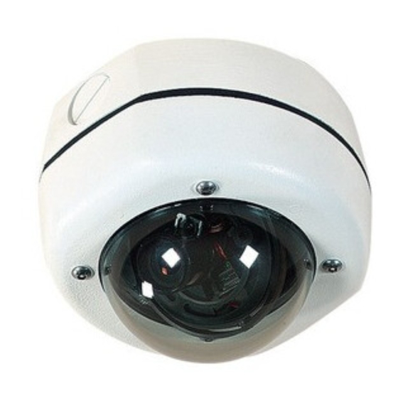
3. DESCRIPTION & SPECIFICATIONS These cameras are small, high security surveillance domes containing 1/3-inch CCD cameras with integral varifocal lenses.The units come ready to use, and mount easily to a wall or ceiling. Construction/Finish: Polycarbonate Dome on cast aluminum housing. 4. - Page 8 Caution: Before proceeding to disconnect the power at its source, be sure that the unit is of the proper voltage type for the line power. Connect 24VAC to the unit by inserting the field supply wires into the 2- position terminal block (supplied) and tighten with a flat blade screwdriver. Connect Video cable to the unit’s BNC connector.
- Page 9 5.3 Mounting and/or Servicing the Unit Refer to Figure 1. Using the rubber base gasket as a template, mark the mounting hole locations on the mounting surface.The unit is intended to be mounted with four #10 screws or four M5 screws (not supplied) through the four outer holes in the base casting.
-
Page 10: Camera Position Adjustment
6. CAMERA POSITION ADJUSTMENT Remove dome cover. Loosen Thumbnuts (x3). Make Pan adjustment by turning camera bracket in clockwise or counter clockwise motion. Tilt Lens into position, then rotate face plate to square image. Tighten Thumbnuts. Square Image Tilt Figure 3 Camera Position Adjustment Points... -
Page 11: Lens Adjustment
LENS ADJUSTMENT 7.1 Adjustment Of Variable Focus Lens 1. Remove the dome cover before lens adjustment. 2.Turn the zoom knob (WIDE< >TELE) to set the field of view angle as desired. See Figure 4. 3. Next, adjust the focus by turning the focus knob (FAR< >NEAR). -
Page 12: Dimensional Outline
153,5 [2.41] [6.04] Threaded for 3/4-inch Conduit 144,3 Plug Supplied [5.68] [3.11] 135,6 [5.34] ©2010 Aigis Mechtronics 1124 Louise Road,Winston-Salem, NC 27107-5450 Tel: 336.785.7740 Fax: 336.785.7744 100 0040 004 AIG 07/10 Data subject to change without notice Printed in U.S.A.
Need help?
Do you have a question about the MLA Series and is the answer not in the manual?
Questions and answers