Table of Contents
Advertisement
Quick Links
Advertisement
Table of Contents

Related Manuals for Swegon BlueBox Omega Sky


Summary of Contents for Swegon BlueBox Omega Sky
- Page 1 Omega Sky Installation, use and maintenance manual 13-05-2020...
- Page 2 THANK YOU Thank you for choosing our product. It is the result of many years’ experience and careful design and has been built with first-class quality materials and advan- ced technologies. Declaration or certificate of conformity also guarantees that the equipment meets the requirements of the European Machi- nery Safety Directive.
-
Page 3: Table Of Contents
Contents Introduction Conformity Description 1.2.1 Symbols 1.2.2 Labels Safety General safety precautions 2.1.1 Discharge of the safety valves 2.1.2 Emergency stop Basic rules 2.2.1 Water flow rate at the heat exchangers 2.2.2 Water composition 2.2.3 Minimum water content in the system 2.2.4 Installing the flow switch 2.2.5... - Page 4 Unintended use Control and safety devices Principles of operation Structure Specifications Control panel 5.7.1 Switching the unit on/off 5.7.2 Changing from cooling to heating 5.7.3 Changing from heating to cooling 5.7.4 Change of set point in cooling operating mode 5.7.5 Change of set point in heating operating mode Wiring diagram Installation...
- Page 5 Preliminary operations 7.1.1 Checking the pre-charge of the expansion vessel 7.1.2 Checking the volume of the expansion vessel 7.1.3 Preliminary operations for LC units 7.1.4 Preliminary operations for the source circuit 7.1.5 Preliminary operations for the FC/NG source circuit First starting 7.2.1 Hydraulic tests 7.2.2...
-
Page 6: Introduction
INTRODUCTION 1.1 Conformity With regard to relevant regulations and directives, see the declaration of conformity that is an integral part of the manual. 1.2 Description 1.2.1 Symbols A description of the main symbols used in this manual and on the labels affixed to the unit is given below. Danger symbol;... -
Page 7: Labels
1.2.2 Labels For the constructional features, available models and technical data, please refer to the Technical Catalogue. The model, serial number, features, power supply voltage and so on are shown on the labels affixed to the unit (the following illustrations are shown only as an example). The Manufacturer adopts a continuous development policy and, in this perspective, reserves the right to make changes and improvements to the documentation and to the units without prior notice. -
Page 8: Safety
SAFETY 2.1 General safety precautions A space of about 2 metres around the unit is identified as external danger zone. If the unit is positioned in an unprotected place that can be reached by unqualified persons, access to this area must be prohibited by special guarding. -
Page 9: Discharge Of The Safety Valves
In units with capacitors and/or inverters, certain components can remain live for several minutes even after having turned off the main switch. Wait 10 minutes before working on the electrical parts of the unit. Circuits supplied from external sources (made with orange cable) can remain live even after the power sup- ply to the unit has been turned off. -
Page 10: Basic Rules
2.2 Basic rules All the units are designed and built in compliance with Directive 2014/68/EU of the European Parliament and of the Council of 15 May 2014 on the approximation of the laws of the Member States relating to pressure equipment. To ensure maximum safety, in order to prevent possible risks, follow the instructions below: - this product contains pressurised vessels, live components, moving mechanical parts and very hot and cold surfaces that, in certain situations, can pose a risk: all maintenance work must be carried out by skilled personnel equipped with... -
Page 11: Water Flow Rate At The Heat Exchangers
2.2.1 Water flow rate at the heat exchangers It is necessary to ensure that the water flow rate during operation is no higher than 1.5 times and no lower than 0.5 times the nominal flow rate of the unit stated in the Technical Catalogue. In any case, refer to the specific Technical Catalogue for the allowed conditions for water flow in and out of the exchangers. -
Page 12: Minimum Water Content In The System
2.2.3 Minimum water content in the system For correct operation of the unit, it is necessary to ensure a buffering on the system such as to comply with the minimum operating time considering the greater between the minimum OFF time and the minimum ON time. In short, these contribute to limiting the number of times the compressors are switched on per hour and to preventing un- desired deviations from the set point of the delivered water temperature. -
Page 13: Installing The Flow Switch
2.2.4 Installing the flow switch Normally, a differential pressure switch is installed between the inlet and outlet of the evaporator in the unit. A flow switch, that must be connected by the installer, can be supplied as accessory. The installed flow switch is provided with a 1” male connector. The unit must be installed following the arrow that shows the direction of flow. - Page 14 On all units, except for the “OH” versions, connect the flow switch to the outlet of the user-side exchanger, indicated in the dimensional diagram and with the relevant plate on the unit. On “OH” version units, connect the flow switch to the outlet of the source-side exchanger, indicated in the dimensional diagram and with the relevant plate on the unit.
-
Page 15: Operation With Water To The Evaporator At Low Temperature
2.2.5 Operation with water to the evaporator at low temperature With temperatures below 5°C, it is mandatory to work with water and anti-freeze mixtures, and also change the safety devi- ces (anti-freeze, etc.), which must be carried out by qualified authorised personnel or by the manufacturer. The glycol percentage by weight is determined based on the desired temperature of the chilled water (see table). Minimum ambient temperature or liquid outlet temperature (°C) Freezing point (°C) -
Page 16: Condensation Control At The Source Hydraulic Circuit
2.2.7 Condensation control at the source hydraulic circuit The temperature and flow rate of the source circuit water must be maintained within the operating limits stated in the Tech- nical Catalogue. It is essential for the water to come in at the connection indicated in the dimensional diagram and with the relevant plate on the unit. - Page 17 As accessory, a two-way modulating valve can be supplied by the manufacturer as an alternative to the three-way valve. The hydraulic connection of the two-way modulating valve must be made as shown in the illustration. Fig. 3 Hydraulic connection of two-way valve Condenser Two-way valve For some sizes, the manufacturer supplies a three-way modulating valve, with way "B"...
-
Page 18: Hydraulic Connection To The Heat Recuperator (Dc Option)
2.2.8 Hydraulic connection to the heat recuperator (DC option) The heat recuperator must be connected to a closed hydraulic circuit. Constant renewal of water causes limescale to build up in the exchanger, which reduces its efficiency in a short time and makes it unserviceable. All units equipped with heat recuperator have water temperature control probe on the return from the system. -
Page 19: Refrigerant Leak Detector
2.2.9 Refrigerant leak detector A refrigerant leak detector with semiconductor sensor can be installed on the units. This device allows immediate detection of refrigerant leaks, with a warning or with stopping of the unit in pump down, de- pending on how it is managed. The installation of the device is in line with European F-GAS regulations and USA ASHRAE regulations. -
Page 20: Noise
2.3 Noise The starting of the unit, with activation of its components, emits a noise whose intensity varies depending on the operating level. The correct location choice and the correct installation prevent the unit causing annoying noise due to resonances, reflections and vibrations. -
Page 21: Safety Information On The Refrigerant Fluid
2.5 Safety information on the refrigerant fluid 2.5.1 Hazards and health consequences If accidentally released, rapid evaporation of the liquid can cause freezing. In case of contact with the liquid: - defrost the various part with water; - remove clothing carefully; - rinse thoroughly with water. Contaminated clothing and shoes should be washed before reuse. -
Page 22: Receiving The Product And Storage
RECEIVING THE PRODUCT AND STORAGE 3.1 Reception On receiving the unit, check that it is undamaged, bearing in mind that it left the factory in perfect condition. Report any signs of damage immediately to the transporter and make a note of these on the Delivery Sheet before signing The relevant sales department or the manufacturer should be informed of the extent of the damage as soon as possible. -
Page 23: Handling
3.3 Handling Before each unit handling operation, check that the lifting capacity of the machinery used is compatible with the weight of the unit. Handling must be carried out by adequately equipped qualified personnel. In all lifting operations, make sure the unit is firmly secured in order to prevent accidental falls or overturning. Lifting must be carried out by qualified and authorised personnel taking the necessary precautions;... -
Page 24: Storage
3.4 Storage The units are built to be installed in indoor environments. Storage outdoors is not allowed. Upon receipt they must be put in locations protected from weather agents. Since the remote condensing unit, if present, is designed to be installed outdoors, it can withstand outdoor atmospheric conditions. -
Page 25: Ecodesign Conformity
ECODESIGN CONFORMITY 4.1 Documentation supplied with the product Listed below are the documents supplied with the machine according to its type, with particular reference to conformity with Directive 2009/125/EC of the European Parliament and of the Council, of 21 October 2009, regarding the establishment of a framework for drafting specifications for the eco-friendly design of energy-related products, and relevant Regulations (hereinafter "Ecodesign"). -
Page 26: Partly Completed Machine
4.1.3 Partly completed machine Units for which conformity with the Ecodesign Directive must be related to a 'partly completed machine plus remote heat exchanger' system. Otherwise, the unit conforms to all EC requirements. All the points described in the first paragraph apply, with the exceptions stated below. The EC Declaration is not accompanied by Attached Documents Conformity with the Ecodesign Directive depends on the combination of partly completed machine plus remote heat exchan- ger and is therefore the responsibility of the person who makes the selection and combination at the installation stage. -
Page 27: Conformity Of The Application
4.2 Conformity of the application The applications allowed as regards the documentation supplied with the unit are indicated below. This applies only in the case of units intended for installation and operation in the European Union. The customer is required to select the unit with regard to the expected operating condition and the Ecodesi- gn conformity required for that condition. -
Page 28: Product Description
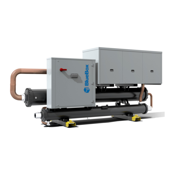
PRODUCT DESCRIPTION 5.1 Intended use These units are intended for cooling (unit in cooling only version) or for cooling/heating (heat pump version) of heat-carrying fluid; they are generally used in applications in the air-conditioning and refrigeration field. These units are made for cooling heat-carrying fluid, and are generally used in applications in the air conditioning and re- frigeration sector. -
Page 29: Control And Safety Devices
5.3 Control and safety devices The unit is integrally managed by an electronic microprocessor control that, through the various temperature and pressure sensors installed in the unit, keeps its operation within the safety limits. All the parameters involved with control of the unit are shown in the “Control Manual” that is an integral part of the docu- mentation of the unit. -
Page 30: Control Panel
5.7 Control panel The unit is integrally managed by an electronic system with microprocessor, having a graphic display as interface. The display can be used to access all the functionalities of the unit starting with the setting of the parameters and manage- ment and analysis of any problems. -
Page 31: Change Of Set Point In Heating Operating Mode
5.7.5 Change of set point in heating operating mode Press the “Menu” button, after the first pressing of the button ENTER move the cursor to the winter setpoint by pressing the button and then confirm with the button ENTER .It is now possible to change the value of the set point, within the set limits, with the buttons The value must be confirmed by pressing the button ENTER... -
Page 32: Installation
INSTALLATION During installation or whenever work must be carried out on the unit, it is essential to strictly follow the instructions in this manual, comply with the directions on the unit and in any case take all necessary precautions. The pressures in the refrigerant circuit and the electrical components can create risky situations during installation and maintenance work. -
Page 33: Installation
6.3 Installation The units are shipped from the factory already tested and they need only the electrical and hydraulic connections for instal- lation, except for the "LC" (condenserless) versions for which the refrigerant connections with the remote heat exchanger must also be made. 6.3.1 Positioning the units The units must be positioned in covered areas where temperatures are kept above 4°C. -
Page 34: Noise Attenuation
6.3.3.2 Spring anti-vibration mounts The cylindrical spring anti-vibration mounts are suitable for isolating any source of mechanical vibration. Each anti-vibration mount bears a code that identifies the maximum load allowed. It is very important to strictly comply with the assembly recommendations and instructions when installing the anti-vibration mounts. -
Page 35: Hydraulic Connections
6.4 Hydraulic connections When preparing to make the hydraulic circuits, it is good practice to comply with the following instructions and in any case follow the national and local regulations (refer to the layouts included in the manual). Fit the pipes to the unit using flexible couplings in order to prevent transmission of vibrations and compensate thermal expansion. -
Page 36: User Hydraulic Circuit
6.4.0 User hydraulic circuit Reference hydraulic diagram for connecting the unit to the user circuit. Fig. 11 Recommended hydraulic circuit Evaporator Water filter Thermometer Motor-driven pump Flow switch Flexible coupling System filling unit Water pressure gauge Valve Safety valve Storage tank Air valve Expansion vessel Check valve... -
Page 37: Source Hydraulic Circuit
6.4.1 Source hydraulic circuit Reference hydraulic diagram for connecting the unit to the source circuit. Fig. 12 Recommended hydraulic circuit Condenser Water filter Thermometer Motor-driven pump Flow switch (mandatory in "HPW" and "OH" versions) Flow switch (mandatory in "HP" versions) Flexible coupling System filling unit Water pressure gauge... -
Page 38: Recovery Hydraulic Circuit
6.4.2 Recovery hydraulic circuit Reference hydraulic diagram for connecting the unit to the recovery circuit. Fig. 13 Recommended hydraulic circuit Heat recuperator Water filter Thermometer Motor-driven pump Flow switch (recommended) Flexible coupling System filling unit Water pressure gauge Valve Safety valve Storage tank with internal heat exchanger Air valve Expansion vessel... -
Page 39: Hydraulic Circuit For Heat Pump Units With Reversal On The Water
6.4.3 Hydraulic circuit for heat pump units with reversal on the water In these units, operation reversal takes place with reversal of the hydraulic circuits. Reversal of the hydraulic circuits can be done using two 4-way valves or four 3-way valves. Fig. 14 Reversal with 4-way valves Fig. 15 Reversal with 3-way valves Whatever solution is adopted, in cooling mode, the evaporator "E"... -
Page 40: Hydraulic Circuits For Fc/Ng Units
6.5 Hydraulic circuits for FC/NG units This line also includes the FC/NG version (Free Cooling No Glycol). In this regard, the "FC/NG kit" or "FC/NG management" can be supplied. In the first case, in addition to management of the function present in the controller, the unit is dispatched from the factory with a decoupling exchanger, three-way valve and source circuit pump(s), already installed and connected. - Page 41 Motor-driven pump with variable flow rate Flow switch Flexible coupling System filling unit Water pressure gauge Valve Safety valve Storage tank 3-way valve servo control Air valve 3-way valve Expansion vessel Check valve It is essential for the water to come in at the connection indicated in the dimensional diagram and with the relevant plate on the unit.
-
Page 42: Unit With "Fc/Ng Kit
6.5.2 Unit with "FC/NG kit" This option includes "FC/NG management". The essential parts for free cooling operation are installed in a module, supplied separately from the unit. The connections of the module to the unit and to the user and source circuits are to be made by the installer. A reference hydraulic diagram is shown below. - Page 43 Storage tank 3-way valve servo control Air valve 3-way valve Expansion vessel Check valve It is essential for the water to come in at the connections indicated in the dimensional diagram and with the relevant plates present on the unit and in the "FC/NG Kit". Failing this, besides running the risk of freezing the evaporator, since control by the antifreeze probe would be thwarted, free cooling operation will be inefficient to the point of causing the protective devices of the unit to trip.
-
Page 44: Electrical Connections
6.6 Electrical connections All electrical operations must be carried out by personnel having the necessary legal requirements, and trained and infor- med on the risks connected with these operations. The sizing and characteristics of the power lines and relevant components must be determined by staff qualified to design electrical systems, following the international and national regulations of the place of installation of the units in conformity with the regulations in force at the time of installation. - Page 45 To fix the power cable, use power cable fixing systems that resist tensile and torsional stresses. The weight of the cables must not be borne by the electrical connection system. Make sure no voltage is present before carrying out any operation on electrical parts. The cross-section of the cable and the line protection devices must correspond to those indicated in the wiring diagram.
-
Page 46: Connections For Multi Free Management
6.7 Connections for Multi Free management Multi Free management includes control of several units, "Master" and "Slave" of a system. To use this function, the units must be suitably connected to the hydraulic system and to the same serial communication network. -
Page 47: Refrigeration Connections
6.8 Refrigeration connections For the "LC" (condenserless) versions, the refrigerant connections must be made between the unit and the remote heat exchanger. The "LC" version units are "dry run" tested, and the refrigerant circuit is charged at the factory with a mixture of nitrogen and helium at a pressure of about 10 bar. -
Page 48: Making The Piping For The Lc Versions
6.8.2 Making the piping for the LC versions Recommended diameters for the LC versions - The thickness of the pipe must be compatible with the refrigerant used and with current regulations. Equivalent length 10 m Equivalent length 20 m Equivalent length 30 m Model Circuits Gas [mm] Liquid [mm] Gas [mm] Liquid [mm] Gas [mm] Liquid [mm] 43.1 50.1 58.1 66.1 70.1 79.1 63.2... -
Page 49: Lc Version: Unit Installed At A Lower Level Than The Remote Exchanger
6.8.3 LC version: unit installed at a lower level than the remote exchanger A summary is given below of the measures to be taken if the unit is installed at a lower level than the condenser: make a well on the delivery line just downline of the compressor to collect the liquid refrigerant that can form during the stops of the unit and can irreparably damage the compressor;... -
Page 50: Vacuum And Refrigerant Charge
6.9 Vacuum and refrigerant charge Open the taps of the unit and evacuate the pre-charge of nitrogen and helium before completing the refrigerant connections. Do not leave the refrigerant circuit open for more than 15-30 min as the high hygroscopic nature of the oil can cause it to absorb moisture that would be detrimental to the circuit. -
Page 51: Topping Up With Oil
Additional refrigerant charges R513A or R134a per linear metre of pipe Diameter (mm) Gas (kg/m) Liquid (kg/m) 0,05 0,91 0,06 1,28 0,11 2,21 0,18 3,51 0,23 4.58 0.33 6.39 0.48 9.38 6.10 Topping up with oil According to the length and diameter of the pipes made for remote exchanger connection, it may be necessary to increase the oil charge. -
Page 52: Commissioning
COMMISSIONING 7.1 Preliminary operations Make sure the main disconnect switch is in the OFF position. Before filling the hydraulic system, check that the drain valve is closed and that all the air valves are open. Open the shut-off devices of the system and start to fill it by slowly opening the water filling valve. When water begins to come out through the air valves, close them and continue filling until the pressure value envisaged for the system is reached. -
Page 53: Checking The Pre-Charge Of The Expansion Vessel
The crankcase heaters are switched on when the main disconnect switch is closed and this must be done at least 12 hours before starting the unit. To check that the heaters are working correctly, check that the lower part of the compressors is hot and in any case at a temperature of 10 - 15 °C above ambient temperature. -
Page 54: Checking The Volume Of The Expansion Vessel
7.1.2 Checking the volume of the expansion vessel As the pre-charge pressure increases, the maximum volume of the system supported by the expansion vessel supplied as standard, decreases. where - VI: volume of the system supported by the expansion vessel [l] - VVE: volume of the expansion vessel [l] - Ce: expansion coefficient of water - pVE: pre-charge pressure of the expansion vessel [barg] - pVS: calibration pressure of the safety valve [barg]... -
Page 55: Preliminary Operations For Lc Units
7.1.3 Preliminary operations for LC units In addition to the previous general checks, further checks are needed for units with remote condenser exchanger: - make sure the fans are turning the right way; - connect the signals of the thermal safety devices of the fans to the terminals arranged inside the electrical control panel of the unit, as shown in the wiring diagram;... -
Page 56: First Starting
7.2 First starting When the unit is started for the first time, some important tests and checks must be done. 7.2.1 Hydraulic tests So that the unit can operate, the external OK signal device must be closed (refer to the wiring diagram provided with the unit). -
Page 57: Functional Tests
7.2.2 Functional tests With the starting of the unit, a few seconds after the starting of the pump, if managed by the control, the compressors will start according to the request of the thermoregulation. After a few hours of operation of the compressors, check that the liquid sight glass has a green ring: if it is yellow, there is moisture in the circuit. -
Page 58: Calibration Of Safety Components
7.3 Calibration of safety components Any work on the unit must be carried out by qualified authorised personnel. Incorrect calibration values can cause serious damage to the unit and harm people. The control and safety equipment is calibrated and tested in the factory before the unit is shipped. However, after the unit has been started, the safety devices must be checked (only the high and low pressure switches). -
Page 59: Checks During Operation
7.4 Checks during operation With the circuits operating at 100% and stable at working conditions near the nominal ones, check: - that the electrical absorption of the unit is close to the data shown in the wiring diagram. Considerably different values may be due to the reduced capacity operation of the unit, at working conditions very different from nominal ones, or to the malfunctioning of one or more components. -
Page 60: Checks During Operation For Fc/Ng Units
7.4.1 Checks during operation for FC/NG units These units are distinguished by their various operating modes for meeting system demand that can take place with ope- ration of the compressors, with free cooling alone or with the combined action of both. The only checks that need to be done regard the refrigerating part. -
Page 61: Alarms And Malfunctions
7.5 Alarms and malfunctions Possible malfunctions will trigger the protective devices and safety devices of the unit before serious faults occur. All the “warnings” and “alarms” are recorded in the memory of the control and displayed on the display of the unit. Before resetting an alarm, the cause that triggered it must be found and eliminated. - Page 62 SYMPTOM LIKELY CAUSE POSSIBLE SOLUTION Check that the high pressure switches Opening of the valve due to failure of are working and, if necessary, replace Presence of oil on the discharge of the the protective devices to operate. them. safety valve. The valve must be replaced.
-
Page 63: Temporary Stop
7.6 Temporary stop The stopping of the unit for a few hours in the day “during non-working hours” or for a few days “over the weekend” is con- sidered temporary. The unit must be stopped using the display of the control, the external OK signal or via serial if included. During the temporary stop, the unit must be powered correctly. -
Page 64: Maintenance
MAINTENANCE All the operations described in this chapter must always be carried out by qualified and authorised person- nel. Before carrying out any work on the unit or accessing internal parts, make sure you have turned off the power supply to it. The compressors and delivery pipes are very hot. -
Page 65: Cleaning The Remote Exchanger
8.2 Cleaning the remote exchanger When there is a remote condenser, the finned heat exchanger is the component of the unit which requires greatest attention. It is essential to keep it clean and free of dirt and/or deposits that can hinder or prevent air flow. Regular cleaning of the surface of the coil is essential for the unit to work correctly and also increases the operating life of the exchanger and the unit. -
Page 66: Periodic Checks
8.4 Periodic checks Carry out periodic checks to make sure the unit is working correctly: RECOMMEN- OPERATION DED FREQUEN- Check the operation of all the control and safety equipment as described previously. Monthly Check the tightness of the electrical terminals in the electrical control panel and in the terminal bo- ards of the compressors. -
Page 67: Unscheduled Maintenance
8.5 Unscheduled maintenance After correctly starting-up and carrying out the relevant checks, the units normally do not need any intervention by the cu- stomer service in order to check the charge of the refrigerant gas. 8.5.1 Special work With use of the unit, particular situations may occur that require work to be carried out promptly. Even in an emergency, work on the unit must be carried out by skilled personnel in safe conditions. -
Page 68: Decommissioning
DECOMMISSIONING With reference to the European waste management directive, we inform you of the following: - The owner of electrical and electronic equipment (EEE) is obliged not to dispose of it as non-separated municipal waste, and must dispose of it via separate collection through public or private waste collection systems as required by local regulations. - Page 69 Page intentionally blank We reserve the right to make changes without any prior notice. Translation from original instructions...
- Page 70 Page intentionally blank Translation from original instructions We reserve the right to make changes without any prior notice.
- Page 71 Page intentionally blank We reserve the right to make changes without any prior notice. Translation from original instructions...
Need help?
Do you have a question about the BlueBox Omega Sky and is the answer not in the manual?
Questions and answers