Table of Contents
Advertisement
Quick Links
Advertisement
Chapters
Table of Contents

Related Manuals for Belden Grass Valley LUMO


Summary of Contents for Belden Grass Valley LUMO
- Page 1 LUMO HIGH DENSITY FIBER CONVERTERS User Manual M974-9900-104 2016-02-18...
- Page 2 Belden Inc. or its affiliated companies in the United States and other jurisdictions. Grass Valley and LUMO are trademarks or registered trademarks of Grass Valley USA, LLC. Belden Inc., Grass Valley USA, LLC, and other parties may also have trademark rights in other terms used herein.
- Page 3 LUMO User Manual Important Safeguards and Notices This section provides important safety guidelines for operators and service personnel. Specific warnings and cautions appear throughout the manual where they apply. Please read and follow this important information, especially those instructions related to the risk of electric shock or injury to persons.
- Page 4 Notices The presence of this symbol in or on Grass Valley product means that it complies with all applicable European Union (CE) directives. The presence of this symbol in or on Grass Valley product means that it complies with safety of laser product applicable standards. Warnings A warning indicates a possible hazard to personnel, which may cause injury or death.
- Page 5 LUMO User Manual • When installing this equipment, do not attach the power cord to building surfaces. • Products that have no on/off switch, and use an external power supply must be installed in proximity to a main power outlet that is easily accessible. •...
- Page 6 Notices Mesures de sécurité et avis importants La présente section fournit des consignes de sécurité importantes pour les opérateurs et le personnel de service. Des avertissements ou mises en garde spécifiques figurent dans le manuel, dans les sections où ils s’appliquent. Prenez le temps de bien lire les consignes et assurez-vous de les respecter, en particulier celles qui sont destinées à...
- Page 7 LUMO User Manual La marque ETL Listed d’Intertek pour le marché Nord-Américain certifie que l’appareil visé a été testé par Intertek et reconnu conforme aux exigences applicables en matière de sécurité électrique en vigueur au Canada et aux États- Unis. Le marquage CE indique que l’appareil visé...
- Page 8 Notices • Après tout travail d’entretien ou de réparation, faites effectuer des contrôles de sécurité par le personnel technique qualifié. Mises en garde Les mises en garde signalent des conditions ou des pratiques susceptibles d’endommager l’équipement. Veuillez vous familiariser avec les mises en garde ci- dessous : •...
- Page 9 LUMO User Manual • Pour plus de sécurité, vérifiez périodiquement la valeur de résistance du bracelet antistatique. Elle doit se situer entre 1 et 10 mégohms. • Si vous devez mettre une carte de côté, assurez-vous de la ranger dans un sac protecteur antistatique.
- Page 10 Notices Electromagnetic Compatibility This equipment has been tested for verification of compliance with FCC Part 15, Subpart B requirements for class A digital devices. Note: This equipment has been tested and found to comply with the limits for a Class A digital device, pursuant to Part 15 of the FCC rules. These limits are designed to provide reasonable protection against harmful interference when the equipment is operated in a commercial environment.
- Page 11 LUMO User Manual Environmental Compliance Restriction on Hazardous Substances (RoHS) FIO-911-4R-LC 有毒有害物质或元素 (Toxic or hazardous Substances and Elements) 六价 多溴联苯 多溴二苯 铅 (Pb) 汞 (Hg) 镉 (Cd) 铬 (Cr6) (PBB) (PBDE) 部件名称 Part name 电路模块 Circuit Modules FIO-911-4T-S13, LC, FIO-911-4TH-CwwCxxCyyCzz-LC 有毒有害物质或元素 (Toxic or hazardous Substances and Elements) 六价...
-
Page 13: Table Of Contents
Table of Contents 1 Introduction ......... . . 1 Introduction to LUMO . -
Page 15: Introduction
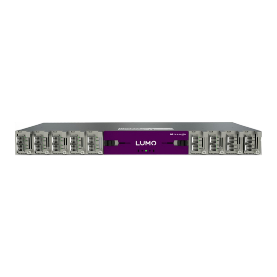
Introduction Chapter 1 is an introduction to the LUMO series of products. Topics Introduction to LUMO ..............page 1 Introduction to LUMO The LUMO is a high-density 1RU frame with 36 SFP-based fiber converters, ideal for large distri- bution of high bandwidth 3Gbps signals. - Page 16 Introduction Introduction to LUMO Cards (maximum 9 per frame) The following cards are available to be used with the LUMO frame: • FIO-911-4T-S13-LC Quad 3Gbps/HD/SD optical transmitter 1310 nm LC/PC connectors • FIO-911-4R-LC Quad 3Gbps/HD/SD optical receiver LC/PC connectors • FIO-911-4TH-CwwCxxCyyCzz-LC High power Quad 3Gbps/HD/SD optical CWDM Tx, LC/PC connector.
-
Page 17: Lumo Housing Frame
LUMO Housing Frame Chapter 2 describes the LUMO housing frame and details of its installation. Topics Overview ................page 3 Features . -
Page 18: Features
LUMO Housing Frame Overview Features • 1 RU with 19” rack mount • Up to 9 cards (72 Watts) • Ease of serviceability • Hot-swappable PSU with optional 2 redundant PSU • Hot-swappable cards, SFPs, controller and fan • Status and alarm over IP with optional LUMO Ethernet Controller •... -
Page 19: Installation
LUMO User Manual LUMO-BNC Rear Panel LUMO-DIN Rear Panel The functionality of Ethernet connectors is described in the Controller card chapter. The details of the rear panel card lexans vary depending on the card type, and are described in Chapter 5. Installation Unpacking Make sure the following items have been shipped with your LUMO frame:... -
Page 20: Assembling The Lumo Frame
LUMO Housing Frame Installation Assembling the LUMO Frame The LUMO frame is shipped with neither the frame mounting brackets nor the fiber support installed. These instructions describe the installation of the rack mounting brackets and the fiber support onto the LUMO frame. The rack mounting brackets may be installed alone (See section A), or in combination with the fiber support. - Page 21 LUMO User Manual B Installing the Fiber Support If you are installing this support onto a LUMO frame which has rack mounting brackets installed, you must remove those brackets first, and then re-install them after the fiber support has been installed, as described in Section C.
-
Page 22: Installing Cards In The Lumo Frame
LUMO Housing Frame Installation C Installing the Rack Mounting Brackets with the Fiber Support After the fiber support is installed, you may install the rack mounting brackets in either of two positions, using four provided screws for each bracket. The figure illustrates the two possible mounting positions. -
Page 23: Field-Serviceable Items
LUMO User Manual in an empty position, first remove the blank card front by unscrewing it and pulling the han- dle straight out of the slot. 2 Slide the new card into the slot and push gently on the handle to seat the connectors. Secure the card in place with the provided front panel captive screw. -
Page 24: Changing The Power Supply
LUMO Housing Frame Field-Serviceable Items Opening and removing the front panel The front panel of the LUMO frame is attached by swivel brackets. Two spring-loaded sliders secure the panel in the closed position. To open the panel, pull the sliders toward the center of the panel, and then pull the panel out until the support brackets allow it to move down below the level of the power supplies. -
Page 25: Replacing Or Upgrading The Controller Card Or Status Card
LUMO User Manual Replacing or Upgrading the Controller Card or Status Card The Controller or Status card is located between the power supply slots at the center of the frame. To replace the card, proceed as follows: 1 Open the center front door, remove the door and push the door mounting brackets back into the frame 2 Hook your finger over the plastic diffuser mounted at the front of the card, and pull out gen- tly until the card is released from the rear connector;... -
Page 26: Specifications
LUMO Housing Frame Specifications • Disconnect the fan power by grasping the connector and pulling straight out. • Remove the two screws that secure the fan unit to the frame and pull the fan unit away from the frame. • Retain the screws, as they will be used with the replacement fan. - Page 27 LUMO User Manual 50/60 Hz 150 W max Ambient Temperature: 40° C max COOLING Fans: 1 on frame, removable COMMUNICATION Connectors: RJ45 (2) Compliant to: 10BaseT/100BaseTx...
- Page 28 LUMO Housing Frame Specifications...
-
Page 29: Status Card
Status Card Chapter 3 describes the installation and functionality of the LUMO chassis status card. Topics Overview ................page 15 Features . -
Page 30: Installation
Status Card Installation Block Diagram The following block diagram shows the functionality of the LUMO status card. Installation The Miranda LUMO-series Status card is installed in the center of the LUMO chassis, between the two power supply slots. To remove or install a LUMO status card, follow these steps: 1 Open the center front door, remove the door and push the door mounting brackets back into the frame 2 Hook your finger over the plastic diffuser mounted at the front of the card, and pull out gen-... -
Page 31: Operation
LUMO User Manual Operation Card-Front Status LED The Status card monitor LED is located on the front card-edge of the LUMO Status card, and is visible through the LUMO frame front panel. This multi-color LED indicates the health status of the LUMO frame by color, and by flashing/steady illumination. -
Page 32: Specifications
Status Card Specifications Specifications PROCESSING PERFORMANCE Microcontroller ARM Cortex-M3 Latency: <1 second Power: <1W... -
Page 33: Lumo-Cpu-Eth Controller Card
LUMO-CPU-ETH Controller Card Chapter 4 describes the installation and functionality of the LUMO-CPU-ETH Controller card in the LUMO housing frame. Topics Overview ................page 19 Features . -
Page 34: Control Interfaces
LUMO-CPU-ETH Controller Card Control Interfaces Ethernet port monitoring, with communication settings and overall bit rate detailed bitrate and communication thoughput from individual cards self-monitoring with CPU load, memory usage Power Supply and fan status reporting • Individual Card parameter storage for easy card swapping •... - Page 35 LUMO User Manual 3 Start a browser on the stand-alone computer, and browse to the LUMO’s factory IP address as given above. The LUMO’s web page will open in the browser.
- Page 36 LUMO-CPU-ETH Controller Card Control Interfaces 4 Select Setup > Ethernet in the menu on the left to open the ethernet setup page. 5 On the SETUP | Ethernet page, enter the required information. Consult your IT department if necessary. Hostname: The hostname is the unique name by which this LUMO is known on the net- work.
-
Page 37: Resetting The Controller
LUMO User Manual Resetting the Controller IMPORTANT: If for any reason you cannot connect to the LUMO frame through the network using the address you have entered: 1 Press the RESET button on the front panel (access it through the cutout on the panel - it is recessed RESET button to protect against accidental acti-... -
Page 38: Using The Icontrol Interface
LUMO-CPU-ETH Controller Card Control Interfaces Using the iControl interface The LUMO-CPU-ETH controller supports remote operation through its two rear-panel 10/100 Base-T ethernet ports, using Miranda’s iControl or a third-party solution. This manual describes the control panels associated with the LUMO-CPU-ETH and their use. Note - you must configure the LUMO-CPU-ETH controller with an appropriate IP address before it can be accessed on your network by iControl. -
Page 39: Card-Front Status Led
LUMO User Manual Card-Front Status LED The status LED is located on the lower-front card-edge of the controller module, and is visible through the front access door of the LUMO frame. This multi-color LED indicates the status of the controller card by color, and by flashing/steady illumination. The table shows how the various error conditions are flagged on the LUMO-CPU-ETH status LED. -
Page 40: Identification
LUMO-CPU-ETH Controller Card Control Interfaces Identification Click the Info button The LUMO-CPU-ETHcontroller is accessible on a network, and must be identifiable in order to function in the iControl environment. The identification data is entered in the iControl INFO control panel. This panel also shows other data that is not user-adjustable. -
Page 41: Status Monitoring
LUMO User Manual Remove: select one of the services listed in the window by clicking on it, and click Remove to open a query box allowing you to delete it from the window. Status Monitoring The LUMO-CPU-ETH controller continuously monitors the operating condition and status of the housing frame’s power supplies and ventilating fans. - Page 42 LUMO-CPU-ETH Controller Card Control Interfaces Status - Frame Select the Frame tab to see a report on the status of the frame’s CPU, fans and power supplies. Status - Network Select the Network tab to see a report on the status of the two Ethernet ports on the LUMO-CPU-ETH card.
- Page 43 LUMO User Manual Status - Cards Select the Cards tab to see a chart of the current send (Tx) and receive (Rx) data rates, and speed, for all cards installed in the LUMO frame. • Note that in the LUMO frame, only slots 1 to 9 are available For a more detailed report on the status of a specific card, open that card’s...
-
Page 44: Network Status
LUMO-CPU-ETH Controller Card Control Interfaces Network Status Click the Network button and select the ETH tab The status of the LUMO-CPU-ETH controller’s two Ethernet ports is displayed in this panel. NOTE: The IP address for the LUMO-CPU- ETH controller must be set using the on- board web page. - Page 45 LUMO User Manual -or- Click the Select All box at the top to activate the feature for all slots in the frame. Click Save to controller at the bottom to copy all restorable data from the cards in the selected slots into the memory on board the LUMO-CPU-ETH controller.
-
Page 46: Factory Alignment
LUMO-CPU-ETH Controller Card Control Interfaces Set up the schedule for data backup using the controls provided. • Schedule: Daily, Weekly, Monthly • Start Time (UTC): Time in hours (24-hour clock) and minutes The label and function of the pulldown at the bottom changes to follow the Schedule selection: Schedule Label Pulldown Options... -
Page 47: Time Management
LUMO User Manual Time Management. The LUMO-CPU-ETH controller is time-aware, and its internal clock can be updated manually or via NTP. Click the Time button Time (UTC) The data boxes in this section display the time and date currently held in the card. - Page 48 LUMO-CPU-ETH Controller Card Control Interfaces The iControl Alarm Configuration panel opens in a new window when the Alarm Config button is clicked, and can be resized if needed. It allows the alarm reporting of the LUMO-CPU-ETH to be configured. The panel is organized in columns. Status/Name This contains an expandable tree listing all the alarms reported by this LUMO-CPU-ETH controller.
- Page 49 LUMO User Manual Log Events iControl maintains a log of alarm events associated with the card. The log is useful for trouble- shooting and identifying event sequences. Click in the checkbox to enable logging of alarm events for each individual alarm. At the bottom of the window are several other controls: Copy to other cards Click this button to open a panel that...
-
Page 50: Specifications
LUMO-CPU-ETH Controller Card Control Interfaces Specifications System Interfaces Status LED Power ON and System Status Ethernet Ports (2) IEEE802.3 10/100 Base-T on RJ45 Power: <3W... -
Page 51: Fio-911 O/E And E/O Converters
FIO-911 O/E and E/O Converters Chapter 5 describes the FIO-911-series optical/ electrical and electrical/opticalconverters that are available for the LUMO housing frame. Topics FIO-911 3G/HD/SD Optical to/from Electrical Converters ......page 37 Features . -
Page 52: Fio-911-4R-Lc
FIO-911 O/E and E/O Converters FIO-911-4R-LC • Presence/loss of signal alarm – iControl, on-board LED for presence • SFP Optical power monitoring and report • Internal SFP temperature alarms on the iControl interface • SFP Module type detection and card configuration •... - Page 53 LUMO User Manual Lexan for BNC frame Lexan for DIN frame The functional block diagram of the FIO-911 Quad Rx model is shown here. Note that the second outputs (A2, B2, C2, D2) are only available on the LUMO-DIN frame. Card-Front Status LEDs These LEDs monitor the status of the optical inputs to the FIO-911 Quad Rx: •...
-
Page 54: Fio-911-4T-S13-Lc
FIO-911 O/E and E/O Converters FIO-911-4T-S13-LC FIO-911-4T-S13-LC Quad 3 Gbps/HD/SD Optical Transmitter 1310 nm with LC/PC connector This variant utilizes two dual optical transmitters at its outputs to send four channels, each of which enters on a rear-panel connector, is equalized, reclocked, E-to-O converted, and sent to the SFP transmitter. -
Page 55: Fio-911-4Th-Cwwcxxcyyczz-Lc
LUMO User Manual Card-Front Status LEDs These LEDs monitor the status of the electrical inputs to the FIO-911 Quad Tx: • Green = SDI signal OK • Yellow = No lock • = No signal • Flashing Red = SFP not present, or SFP not detected, or hardware failure FIO-911-4TH-CwwCxxCyyCzz-LC High Power Quad 3 Gbps/HD/SD Optical CWDM Transmitter with LC/PC connector... - Page 56 FIO-911 O/E and E/O Converters FIO-911-4TH-CwwCxxCyyCzz-LC The front panel and rear lexans (DIN and BNC) for this model are shown below. Note that they are identical to those for the FIO-911-4T-LC model. The clasp handles on the SFP modules are color-coded to identify their wavelengths, and this will serve to distinguish the two FIO-series products.
-
Page 57: Icontrol Interface
LUMO User Manual iControl Interface When installed in a LUMO frame equipped with a LUMO-CPU-ETH controller card and connected to a network (see Chapter 4), the FIO-911 cards may be remotely monitored and controlled using Miranda’s iControl system. To use iControl with the FIO-911 cards, proceed as follows: 1 Install and configure your LUMO-CPU-ETH controller for network access to enable the iCon- trol interface. - Page 58 FIO-911 O/E and E/O Converters iControl Interface Status The Status window shows the status of the four inputs to the card. One tab shows the status of inputs A and B, and the status of their associated SFP module, while a second tab provides the same information for inputs C and D.
- Page 59 LUMO User Manual Factory Reset The FIO-911 card can be reset to factory- specified settings of all on-board parame- ters by clicking the Load Factory button. Alarm Configuration The FIO-911 card detects and signals alarm conditions. A status LED is positioned beside each fiber connection to the SFP module on the front panel of the card.
- Page 60 FIO-911 O/E and E/O Converters iControl Interface Overall Alarm This column allows configuration of the contribution of each individual alarm to the Overall Alarm associated with this card. The Overall Alarm is shown in the upper left corner of the iCon- trol panel, and also appears at the bottom of the Status/Name column.
- Page 61 LUMO User Manual Levels associated with these alarms: The alarm status list may contain some or all of the following options: Alarm status Significance The alarm makes no contribution (black icon) The alarm is of minor importance (yellow icon) The alarm is of major importance (orange icon) The alarm is of critical importance (red icon) The alarm exists but has no effect (used for text and composite alarms) Shortcut: if you click on “Set All”...
- Page 62 FIO-911 O/E and E/O Converters iControl Interface Get alarm keys Click this button to open a save dialog where you can save a file containing a list of all alarms on this card and their current values, along with an Alarm Key for each.
- Page 63 LUMO User Manual The remaining data boxes show manufacturing information about this card. Three buttons in the panel give access to other information: Details: Reports the Firmware version, service version, and panel version for this card Advanced: Shows the Miranda LongID for this card. The Miranda LongID is the address of this FIO-911 card in the iControl network.
-
Page 64: Specifications
FIO-911 O/E and E/O Converters Specifications Specifications ELECTRICAL INPUT Signal: 3G/HD/SD SDI SMPTE 424M, 292M, and 259M- C compliant Supported data rates: Reclocker bypassed – all rates between 19.4 Mbps and 3 Gbps Reclocked data at 270, 1483.5, 1485, 2967, 2970 Mbps EN50 83-9 DVB-ASI 270 Mbps Return loss:... - Page 65 LUMO User Manual OPTICAL I/O Optical: SMPTE-297M-2006 compliant 3G/HD/SD SDI: SMPTE-424M SMPTE-292M and SMPTE-259M-C Compliant RX CHANNEL (PATHOLOGICAL BITSTREAM) Sensitivity between 1260 and 1610 nm: SD, HD and 3 Gbps: -22 dBm Tx CHANNEL (1310 nm) Transmit power: -5 dBm to 0 dBm Laser type: Fabry-Perot Tx CHANNEL (CWDM)
- Page 66 FIO-911 O/E and E/O Converters Specifications...
-
Page 67: Sfp Modules
SFP Modules Chapter 6 presents information regarding the use of SFP modules in LUMO-series cards. Topics Introduction ............... . page 53 Cautions and Warnings . -
Page 68: Installing An Sfp Module
SFP Modules Installing an SFP module Installing an SFP module 1 Make sure that the bale clasp lever is in the closed position 2 Position the SFP module so that the recessed slot is lined up with the tab side of the socket. 3 Slide the module straight into the socket, and push gently until it clicks into position. -
Page 69: Removing The Fiber Optic Cables
LUMO User Manual Removing the fiber optic cables 1 Grasp the LC fiber optic connector that is plugged into the SFP module, and pull it straight out to disengage the optical fiber from the SFP. • Never pull the fiber optic cable itself, as catastrophic damage may occur. 2 Insert a dust plug into the SFP module. -
Page 70: Keep The Connection Clean
SFP Modules Removing an SFP module Keep the connection clean! The physical interface between two optical fibers is the critical point in a fiber system. The two fibers must be accurately aligned – that’s the job of the connector plugs and bulkheads – and be in intimate contact with no obstructions. -
Page 71: Contact Us
Contact Us Grass Valley Technical Support For technical assistance, contact our international support center, at 1-800-547-8949 (US and Canada) or +1 530 478 4148. To obtain a local phone number for the support center nearest you, please consult the Contact Us section of Grass Valley’s website ( www.grassvalley.com An online form for e-mail contact is also available from the website.
Need help?
Do you have a question about the Grass Valley LUMO and is the answer not in the manual?
Questions and answers