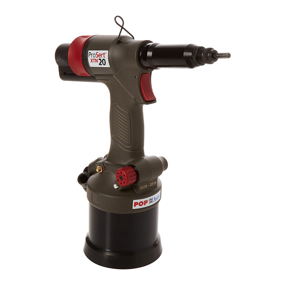
Stanley ProSert XTN20 Service Manual
Blind rivet nut tool hydro-pneumatic power tool
Hide thumbs
Also See for ProSert XTN20:
- Instructions manual (144 pages) ,
- Service manual (92 pages) ,
- Instruction manual (72 pages)

Related Manuals for Stanley ProSert XTN20


Summary of Contents for Stanley ProSert XTN20
- Page 1 Service Manual Original Instruction Hydro-Pneumatic Blind Rivet Nut Tool ProSert® XTN20 Blind Rivet Nut Tool – 74202 Hydro-Pneumatic Power Tool...
- Page 2 E N G L I S H Fig. 1 12 13 Fig. 2...
- Page 3 E N G L I S H Fig. 3...
- Page 4 E N G L I S H Fig. 4...
- Page 5 E N G L I S H Fig. 5...
- Page 6 E N G L I S H...
- Page 7 E N G L I S H Fig. 6...
-
Page 8: Table Of Contents
STANLEY Engineered Fastening will not accept any liability for damage resulting from activities carried out by third parties. The working names, trade names, registered trademarks, etc. used by STANLEY Engineered Fastening should not be considered as being free, pursuant to the legislation with respect to the protection of trade marks. -
Page 9: Safety Definitions
SAVE THESE INSTRUCTIONS. WARNING: Do not use outside the design intent of Placing STANLEY Engineered Fastening Blind Rivet Nuts. Use only parts, fasteners, and accessories recommended by the manufacturer. Do not modify the tool in any way. Any modification to the tool is undertaken by the customer and will be the customer’s entire responsibility and void any applicable warranties. - Page 10 20. Do not abuse the tool by dropping or using it as a hammer. 21. Keep dirt and foreign matter out of the hydraulic system of the tool as this will cause the tool to malfunction. STANLEY Engineered Fastening policy is one of continuous product development and improvement and we reserve the right to change the specification of any product without prior notice.
-
Page 11: Specification
E N G L I S H 2. Specification The ProSert® XTN20 hydro-pneumatic tool is designed for placing STANLEY Engineered Fastening Blind Rivet Nuts through adjustment of the force and/or the stroke. The ProSert® XTN20 Tool is used to place Blind Rivet Nuts from a range of M3 to M10 when coupled with the relevant nose equipment. -
Page 12: Main Components List
E N G L I S H 2.3. Main components list Re-order Thread Part Nr. Desctription Spare part numbers 07555-09004 07555-09005 Mandrel 07555-09006 07555-09008 07555-00904 07555-00905 Nose Tip 07555-00906 07555-00908 Lock Nut 07555-00901 Nose Casing 74202-02021 Chuck Nut 74202-02022 07555-09104 07555-09105 Reducing Sleeve 07555-09106... -
Page 13: Tool Setup
E N G L I S H 3. Tool Setup IMPORTANT - READ THE SAFETY RULES ON PAGE 9 & 10 CAREFULLY BEFORE PUTTING INTO SERVICE. Before Use • Select relevant size nose equipment and install. • Connect the placing tool to the air supply. Test pull and return cycles by depressing and releasing the trigger 12. -
Page 14: Air Supply
E N G L I S H 4.2 Air Supply • All tools are operated with compressed air at an minimum pressure of 5.0 bar. • Pressure regulators and automatic oiling/filtering systems to be used on the main air supply within 3 metres of the tool (see fig. -
Page 15: Operating Procedure
E N G L I S H 4.3.1. Stroke Adjustment (see Fig. 1A & 3). To use this tool in stroke set operation, screw the Pressure Regulator 30 fully in to achieve full pressure then adjust Stroke Setter to the desired stroke length: Open Stroke Slider 20B •... -
Page 16: Servicing The Tool
E N G L I S H 6. Servicing the Tool Regular servicing must be carried out by trained personnel and a comprehensive inspection performed annually or every 500,000 cycles, whichever is sooner. Cleaning and Maintenance DISCONNECT AIR SUPPLY Nose assemblies should be serviced at weekly intervals or every 5,000 cycles CAUTION - Blow dirt and dust out of the main housing with dry air as often as dirt is seen collecting in and around the air vents where the Pneumatic Cylinder connects to the plastic Handle Assembly. -
Page 17: Priming
E N G L I S H 6. 3 Priming Priming is necessary after the tool has been dismantled and prior to operating. It may also be necessary to restore the full stroke after considerable use, if the stroke has been reduced and fasteners are not now being fully placed by one operation of the trigger. -
Page 18: Maintenance
E N G L I S H 7. Maintenance I M P O R TA N T SAFETY INSTRUCTIONS APPEAR ON PAGE 9 & 10. THE EMPLOYER IS RESPONSIBLE FOR ENSURING THAT TOOL MAINTENANCE INSTRUCTIONS ARE GIVEN TO THE APPROPRIATE PERSONNEL. THE OPERATOR SHOULD NOT BE INVOLVED IN MAINTENANCE OR REPAIR OF THE TOOL UNLESS PROPERLY TRAINED. - Page 19 E N G L I S H Regulator Unwind Pressure Switch 30 to its full extent. • Using a 2mm Hexagonal Wrench unscrew Screw 74 remove Pressure Switch 30 Regulator Lock 31, Spring 32 and Locking Bearing 33. Using a 14mm Spanner unscrew the Pressure Catch 28 the Regulator 29 should then be unscrewed •...
- Page 20 E N G L I S H AIR INLET ASSEMBLY 74202-02103 POSITION PART NUMBER DESCRIPTION SPARES 74202-02100 AIR FILTER 07003-00026 O RING 74202-02096 1/4 CONNECTION 07003-00029 O RING 74202-02097 MALE CONNECTION 74202-02099 CIRCLIP 74202-02098 FEMALE CONNECTION DISTRIBUTOR ASSEMBLY 74202-02105 POSITION PART NUMBER DESCRIPTION SPARES...
- Page 21 E N G L I S H AIR MOTOR ASSEMBLY 74202-02104 POSITION PART NUMBER DESCRIPTION SPARES 74202-02028 MOTOR CASE 74202-02110 HOUSING 07555-09216 74202-02111 HOUSING BLOCK 07555-09215 BEARING 74202-02112 MOTOR VANE 74202-02113 MOTOR SPINDLE 07555-09210 WASHER 07555-09206 BEARING 74202-02115 WASHER 74202-02116 RING GEAR 74202-02117 PLANET GEAR...
-
Page 22: Troubleshooting Guide
E N G L I S H 8. Troubleshooting guide Symptom Possible Cause Remedy Page Ref. Air leak from motor. Check for worn seals. Replace. Low air pressure. Increase air pressure. Pneumatic motor runs slowly. Air way blockage. Clear restriction. Motor Vanes 6M jamming Clean and lubricate. -
Page 23: Hydraulic Oil General Safety Data
You can check the location of your nearest authorised repair agent by contacting your local STANLEY Engineered Fastening office at the address indicated in this manual. Alternatively, a list of authorised repair agents and full details of our after-sales service and contacts are available on the Internet at: www.StanleyEngineeredFastening.com... - Page 24 The names and logos of other companies mentioned herein may be trademarks of their respective owners. Data shown is subject to change without prior notice as a result of continuous product development and improvement policy. Your local STANLEY Engineered Fastening representative is at your disposal should you need to confirm latest information.
Need help?
Do you have a question about the ProSert XTN20 and is the answer not in the manual?
Questions and answers