Advertisement
Available languages
Available languages
Quick Links
GENERAL INFORMATION
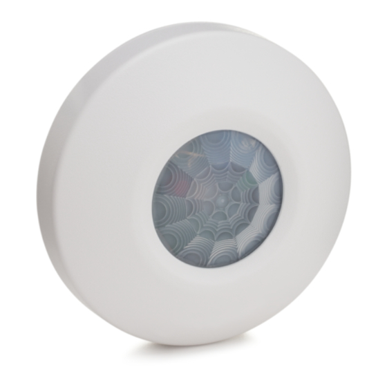
This passive infrared motion detector is a ceiling-mounted
unit employing a 360°, 31-zone Fresnel lens and offering an
efficient protection pattern for commercial and residential
applications. The detector senses sudden and slight
changes in temperature within the area of detection; thus,
when an intruder crosses or enters any zone, the resulting
change in infrared energy is detected for alarm reporting.
Best coverage will be obtained if the PIR is mounted such
that the likely direction of intruder motion is in the direction
shown in Figure 1.
The Detector features installer-selectable Alternate Polarity
Pulse Count, which provides protection against false alarms,
and an LED enable/disable feature (installer-selectable).
INSTALLATION HINTS
• Do not install where the detector is exposed to direct
sunlight or directly above strong sources of heat.
• Make sure the detection area does not have obstructions
(curtains, screens, large pieces of furniture, plants, etc.)
that may block the pattern of coverage.
• Avoid locating a detector in areas that contain objects
likely to produce a rapid change in temperature, such as
central heating, radiators or ducts (or heaters of any kind),
air conditioners, open flame, etc.
• Do not mount on an unstable surface.
Important: Avoid running alarm wiring close to heavy-duty
electrical power cables.
PROTECTION PATTERNS
The PIR's protection pattern is shown below.
Detection Area
TOP VIEW
12 ft
8 ft
HEIGHT
HEIGHT
(3.66m)
(2.4m)
18 ft
11.5 ft
(5.5m)
(3.5m)
0
18 ft
11.5 ft
(5.5m)
(3.5m)
CENTER ZONE
ZONES B (6 ZONES)
ZONES C (12 ZONES)
ZONES D (12 ZONES)
SIDE VIEW
SPECIFICATIONS
Detection Method: Passive Infrared.
Coverage:
23-ft (7m) diameter @ 8 ft (2.4m) height,
11.5-ft (3.5m) radius.
36-ft (11m) diameter @ 12-ft (3.7m) height,
18-ft (5.5m) radius.
Pulse Count:
1- or 2-event, installer-selectable.
Detectable
Walk Rate:
0.5 – 5ft/Sec (0.15 – 1.5m/Sec).
Indicator:
Red LED with enable/disable feature.
Mounting
Height:
12-ft (3.7m) maximum
Voltage:
12VDC nominal (voltage reversal makes
PIR inoperative).
Alarm Relay:
SPST, Form A, 0.5A max. contact rating @
30VDC. Reed relay, 15 ohm protective
resistor.
Current Drain:
17mA.
Standby
Capability:
Power source should be capable of at least
4 hours of battery standby.
Operating
Temperature:
32°F – 122°F (0°C – 50°C).
Operating
Humidity:
Up to 95% RH (max), non-condensing.
Dimensions:
3-1/2" (89mm) diameter x 1" (25.4mm) high.
INSTALLING AND WIRING THE PIR
The ceiling on which the PIR is to be mounted must be firm
and vibration-free.
1. Select a location that will provide the coverage desired.
Wiring (from the control, etc.) to be connected to the PIR
should be brought to this location. The ceiling wiring hole
should be no more than 5/16" (8mm) in diameter.
2. Remove the cover from the PIR by pressing it in gently
and turning it counterclockwise (to the left). To replace the
cover, align the tabs on the cover's edge with the notches
on the base's rim, press the cover gently in, and turn it
clockwise (to the right).
INSTALLATION INSTRUCTIONS
3. Break out one of the two knockouts that have been
provided for wire access (see Figure 3), and pass the
wires into the base of the PIR. Caution: Be certain that
wires do not obstruct the detector's field of view.
4. Connect all wires to the screw terminals (see Figure 3 for
wiring details). Seal all openings in the base with foam or
RTV (not supplied) to prevent drafts or insects from
entering the unit.
5. For walk-test purposes, initially set the LED to "on"
(jumper removed), and set Pulse Count "off" (jumper
removed).
6. Mount the PIR base to the ceiling with two screws, using
the screw holes provided in the base of the PIR.
Important Note: Optimum mounting orientation is shown in
Figure 1. Mount the PIR in such a manner that the likely path
of an intruder is in the direction shown. This will ensure
maximum effectiveness of the Alternate Polarity feature.
INTRUDER'S MOST LIKELY DIRECTION OF MOTION
PULSE
COUNT
Figure 1. Optimum Mounting Orientation
LED ENABLE/DISABLE
The detector is shipped with the Alarm LED disabled (LED
enable/disable plug in place). The LED should be enabled (for
a walk-test) by removing the LED enable/disable plug (see
Figure 3 for location). To prevent the loss of the plug, we
NOTE: EACH ZONE
CONSISTS OF TWO
suggest you install it on one pin when the plug is not in use.
FIELDS (INCLUDING
When the walk-test is completed, the LED may be disabled, if
THE CENTER ZONE)
desired (plug in place).
The LED may also be controlled from a remote location, as
follows:
Remove the LED enable/disable plug. Connect a switched
line to the upper pin (#1) of the two LED pins that can be
grounded or opened (see Figure 2). Grounding pin #1 will
disable the LED. Disconnecting it from ground will enable the
LED.
997-004-V0
RELAY
12V
TO A GROUND TERMINAL ON THE ASSOCIATED
CONTROL OR TO ( ) TERMINAL ON DETECTOR
Figure 2. Remote Control of LED
TAMPER SWITCH
This PIR is equipped with a cover tamper switch. With
cover on, the switch is closed; when cover is removed, the
switch opens. The tamper terminals (see Figure 3) should
be connected to the control panel's tamper loop.
PULSE COUNT OPTION
Each detector includes Pulse Count circuitry that is
designed to provide stability in adverse environments to
minimize false alarms. Two-event pulse count is provided
by positioning the jumper plug across the pulse count pins
(see Figure 3 for location). To select one-event pulse count
(instant response), remove the jumper plug. When
programmed for 2-event pulse count, the detector will
signal an alarm within 3 or 4 steps, since the processing
logic requires more complex motion than just a momentary
event. When the detector verifies an intrusion, the LED will
light and the alarm relay contacts will transfer, both
conditions lasting for approximately 1 to 3 seconds
(dependent upon signal strength).
To prevent the loss of the plug, we suggest you install it on
one pin when the plug is not in use.
KNOCKOUTS (2)
FOR WIRE ENTRY
PULSE COUNT
"ON" WITH PLUG
INSTALLED."OFF"
WITH PLUG
REMOVED.
TO CLOSED CIRCUIT
PROTECTIVE LOOP
Figure 3. PC Board (in base of PIR)
Ceiling-Mounted Passive Infrared Motion Detector
ON
LED
OFF
DET
LED
ALARM
RELAY
12V
997-001-V0
1
LED
DISABLE
ENABLE
997-002-V0
MOUNTING
HOLES (2)
LED
"OFF" WITH
LED
ON
PLUG
INSTALLED.
"ON"
DET
OFF
LED
WITH PLUG
REMOVED.
ALARM
TAMPER SWITCH
(OPENS WHEN
RELAY
COVER IS
12V
REMOVED).
TO SEPARATE
TAMPER CIRCUIT
TO 12VDC
+ POWER SOURCE
997-003-V0
TEST PROCEDURES
Important: Two-minute warm-up time is required after
applying power. Testing should be conducted with the
protected area cleared of all people. Disarm the protective
system's control during the test procedure to prevent
reporting of unwanted alarms.
Walk-Test
1. Pulse Count in the PIR must be "OFF" (jumper plug
removed) to provide instant response. The Alarm LED
must be enabled at this time (LED jumper plug removed).
2. With the cover installed on the PIR, walk through the
protective zones, observing that the PIR's LED lights
whenever motion is detected (the LED serves as a walk-
test indicator during this procedure).
Note: With pulse count "OFF" (instant), the LED stays lit
(and
the
alarm
relay
contacts
approximately 1 to 3 seconds after detecting motion.
3. If pulse count is to be used in this installation, install the
pulse count jumper plug on the pulse count pins, and
repeat the walk test procedure. With pulse count "ON,"
the LED serves as an alarm indicator.
The absolute range of all PIR units is subject to variation
because of different types of clothing, backgrounds and
ambient temperature. For this reason, ensure that the most
likely intruder routes are well within the PIR's protective
zones and that walk-testing is carried out along these routes.
After the walk-test is complete, the LED may be disabled if
desired (LED enable/disable plug installed).
MAINTAINING PROPER OPERATION
In order to maintain the detector in proper working condition,
it is important that the following be observed by the user.
1. Power should be provided at all times. Loss of power
to the unit will result in the alarm contacts reverting to an
alarm state. The unit's DC source should have standby
power available for at least 4 hours of operation during
emergencies.
2. Units should never be relocated without the advice or
assistance of the alarm service company.
3. The physical surroundings of the protected area
should not be changed. If furniture or stock is moved,
or air-conditioning or additional heating is installed, the
system may have to be readjusted by the alarm service
company.
4. Walk-tests should be conducted frequently (at least
weekly) to confirm continued proper coverage by each
detector.
TROUBLESHOOTING
INTERMITTENT ALARM (LED OPERATIVE)
Probable Causes:
A. Rapid temperature change. Check for electric or gas
heaters, open flames, electric arcs, etc..
Remedy: Locate source and reposition detector if
necessary.
B. Drafts causing drapes, light fixtures, display material to
move.
Remedy: Eliminate source of motion.
INTERMITTENT OR CONTINUOUS ALARM
Probable Causes:
A. DC
voltage
supplied
to
detector
intermittent, or polarity reversed.
Remedy: Ensure that proper polarity and adequate
voltage is supplied and that wiring is intact (no
opens or shorts) and connections secure.
B. Protective loop is interrupted (open).
Remedy: Determine whether interruption is in protective
loop wiring or at detector's alarm relay
contacts. Disconnect protective loop at detector
relay contact terminals and check continuity
across terminals. If absent at terminals (and
proper voltage is supplied to the detector),
return unit for service. If present, check
protective loop wiring.
LED INOPERATIVE
Probable Causes:
A. LED enable/disable plug is installed.
Remedy: Remove LED enable/disable plug.
B. LED malfunction. Check for broken/shorted leads.
Remedy: Return unit for service.
NO ALARM WHEN MOTION TAKES PLACE IN THE
PROTECTED AREA (LED DOES NOT LIGHT)
Probable Causes:
A. Detection area has changed. Possibly due to repositioned
furniture or equipment in the protected area.
Remedy: Caution customer about layout changes.
WARRANTY INFORMATION
For the latest warranty information, please go to:
www.honeywell.com/security/hsc/resources/wa
997
remain
open)
for
is
inadequate,
Advertisement

Related Manuals for Honeywell 997


Summary of Contents for Honeywell 997
- Page 1 After the walk-test is complete, the LED may be disabled if electrical power cables. RELAY desired (LED enable/disable plug installed). PROTECTION PATTERNS 997-001-V0 The PIR’s protection pattern is shown below. MAINTAINING PROPER OPERATION Figure 1. Optimum Mounting Orientation In order to maintain the detector in proper working condition, Detection Area it is important that the following be observed by the user.
- Page 2 OFF (quitar puente) para respuesta www.honeywell.com/security/hsc/resources/wa base, presione suavemente la cubierta y gírela en sentido instantánea. El LED de alarma debe estar habilitado de las agujas del reloj (hacia la derecha).
- Page 3 3. Si la fonction de comptage d'impulsions est nécessaire, 6. Fixer l'embase du détecteur au plafond avec deux vis, en intempestifs, le 997 est doté d'une fonction de comptage effectuer le réglage approprié en plaçant le cavalier dans utilisant les trous prévus à cet effet.
- Page 4 (rechtsom). ÊN6206-1V1gŠ 2 Corporate Center Drive, Suite 100 P.O. Box 9040, Melville, NY 11747 Copyright © 2010 Honeywell International Inc. www.honeywell.com/security N6206-1V1 3/10 Rev A...
Need help?
Do you have a question about the 997 and is the answer not in the manual?
Questions and answers