Advertisement
Quick Links
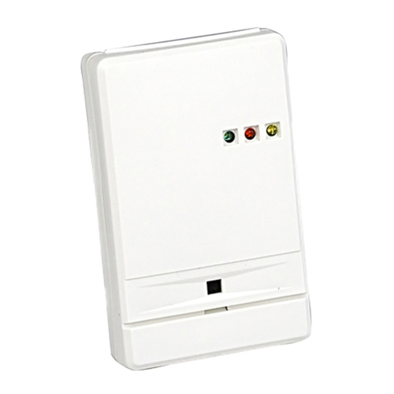
The FG-730 is a dual technology glassbreak detector that uses flex
detection and audio discrimination to detect breaking glass.
The flex and audio technologies are sensitive to different frequencies. The
flex technology is sensitive to ultra low frequencies, the type generated by
a blow to a glass window. The audio technology detects the frequency of
breaking glass.
The audio technology remains off until the flex technology detects a blow
to the glass. For an alarm condition to occur, the audio must detect the
frequency of breaking glass within a defined time-window after the flex
detects a blow to the glass. Because both technologies must detect and
verify glass breakage, false alarms are virtually eliminated.
.
FEATURES
.
Dual flex/audio technology
Low 10 - 14 VDC operation
.
Low 25 mA at 12 VDC current
.
draw
No adjustment on audio
.
Adjustment on flex detection
to fit characteristics of each
location
MOUNTING LOCATION
The FG-730 can be mounted on walls, in corners, even on false or suspended
ceilings. Refer to the guidelines below when selecting a mounting location.
.
The unit must have a direct line of sight to, and a clear view of,
the protected glass.
.
Locate the FG-730 within 30' (9 m) of the glass to be protected.
.
Curtains, blinds, and other window coverings will absorb energy
from breaking glass. Heavy curtains, for example, will effectively
block the sound signal. In these cases, mount the unit on the window
frame behind the window covering, or above the window. Make
sure to test the unit thoroughly for proper detection.
.
Do not mount the unit in front of air ducts or forced air fans, or
close to bells measuring 2" (5 cm) or larger in diameter.
MOUNTING PROCEDURE
Orient the unit as shown in Figure 1. Remove the screw located at its top.
While depressing the latch near the top of the unit, swing the front cover
forward. Use the back cover as a template to mark holes for the mounting
screws and wiring, then drill the holes.
.
Note: If you plan to corner-mount the unit, remove the printed
circuit board before marking and drilling holes for the mounting
screws.
FlexGuard
Dual Technology
®
Glassbreak Detector
INSTALLATION INSTRUCTIONS
Model
FG-730
30' range
.
Alarm memory
.
Indicator LEDs
.
Energized form C alarm relay
.
Circuit protection
.
Cover tamper switch
.
.
Noise burst rejection circuit
RFI immunity
.
UL listed
Pull the wiring into the unit through the back cover. Using the two mounting
screws, mount the rear housing at the desired location.
After removing screw at top of
unit, depress this latch to open
housing
Figure 1
Mounting
the FG-730
WIRING
Observing the proper polarity, wire the unit as shown in Figure 2 (use 22
to 14 AWG). Reverse-polarity connections will not damage the unit.
Tamper
Form A (NC)
50 mA, 30 VDC
Alarm
Form C
500 mA max, 30 VDC max,
30 VA max
Power
10 - 14 VDC
25 mA, 12 VDC
Figure 2 FG-730 Terminal Strip
FLEX ADJUSTMENT
To adjust the flex technology: Use a screwdriver to set the flex sensitivity
control (R5) at MAXIMUM by turning it all the way clockwise. Refer to Figure
3 on the back side of this page.
Turn on any heating/air conditioning system in the vicinity and observe the
yellow flex LED (DS2) for approximately one minute. Excessive subsonic
(inaudible) noise typically produced by air handling systems may cause
the flex LED to flash randomly.
If it flashes randomly, turn the R5 control counterclockwise just until the
flashing stops.
TESTING THE FG-730
Use the FG-701 Glassbreak Simulator to test the FG-730 detector. The FG-
700 may also be used.
Activate the simulator in MANual mode at the farthest point of the glass to
be protected (30' maximum). If the green LED (DS1) on the detector
flashes, the audio technology will detect breaking glass at that distance.
Test the flex technology by carefully striking the glass with a cushioned tool.
If the yellow LED on the detector flashes, the flex technology will be sensitive
enough to detect a blow to the glass at that distance.
REAR HOUSING
For surface mounting
For corner mounting
(score and pull flap open)
Knockouts
FRONT HOUSING
NC
C
NO
C
NC
V-
V+
Advertisement

Related Manuals for Honeywell FG-730


Summary of Contents for Honeywell FG-730
- Page 1 MOUNTING LOCATION FLEX ADJUSTMENT The FG-730 can be mounted on walls, in corners, even on false or suspended To adjust the flex technology: Use a screwdriver to set the flex sensitivity ceilings. Refer to the guidelines below when selecting a mounting location.
- Page 2 Please contact your local authorised Honeywell representative for product warranty information. 5-051-169-00 7/14 Rev. J © 2004 Honeywell International Inc. • Honeywell, IntelliSense and DUAL TEC are registered trademarks of Honeywell International Inc. All other trademarks are the properties of their respective owners. All rights reserved.
Need help?
Do you have a question about the FG-730 and is the answer not in the manual?
Questions and answers