
Related Manuals for Banner SX5-ME70


Summarization of Contents
1 About This Document
1.1 Important... Read This Before Proceeding!
Emphasizes the importance of reading the manual for safe installation, operation, and maintenance.
1.2 Use of Warnings and Cautions
Explains the meaning of signal words and alert symbols for safe use of the scanner.
1.3 EU Declaration of Conformity (DoC)
Declares product conformity with EU directives and health/safety requirements.
2 Product Overview
2.1 Models
Lists and describes available SX Series Safety Laser Scanner models and required accessories.
2.1.1 Features
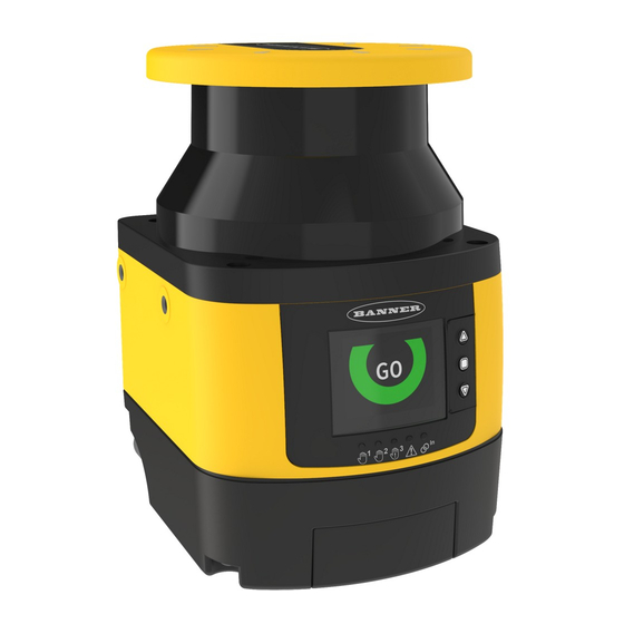
Highlights key physical features of the SX Series Safety Laser Scanner.
2.1.2 Scanner Limitations
Details environmental and operational limitations for safe and effective use of the scanner.
2.1.3 Product Specification Label
Describes the information found on the product identification plate.
2.2 Documents List
Lists related documents available for applying and configuring the SX Series Safety Laser Scanner.
2.3 Appropriate Applications and Limitations
Provides crucial information on suitable applications and restrictions for the SX Series Safety Laser Scanner.
2.3.1 Appropriate Applications
Lists suitable applications and potential uses for the SX Series Safety Laser Scanner.
2.3.2 Control Reliability: Redundancy and Self-Checking
Explains the scanner's redundant microprocessors and self-checking system for safety.
2.3.3 Application Checklist
Provides a checklist to ensure proper application, settings, and coordination for the SX Series Safety Laser Scanner.
2.3.4 Sample Applications
Presents sample applications, focusing on Stationary Area Guarding for instructional purposes.
2.3.5 Applications with Master and Remote Scanners
Describes how to use multiple scanners for monitoring various zones in a single system.
2.4 Operating Features
Outlines key functions and features of the SX Series Safety Laser Scanner models.
2.5 Memory Device for the Master Models
Explains the function and use of the removable memory device for master scanner models.
2.6 Reference Points (Surface) Monitoring
Details the reference point monitoring function to prevent misalignment and manipulation.
2.7 Passwords
Explains the password protection for the SX scanner configuration to prevent accidents.
2.8 Laser Safety (Class 1)
States that the SX Series Safety Laser Scanner uses a Class 1 laser.
2.8.1 Class 1 Lasers
Defines Class 1 lasers as safe under foreseeable conditions, including optical instruments.
2.8.2 For Safe Laser Use (Class 1 or Class 2):
Provides essential safety instructions for using the laser scanner safely.
2.9 Software Overview
Introduces the configuration software for setting up the SX scanner and viewing system information.
2.9.1 System Requirements
Lists the minimum PC hardware and software requirements for using the SX configuration software.
2.9.2 Safety and Warning Zones
Explains the purpose and configuration of Safety Zones and Warning Zones in the software.
2.9.3 Monitored Space Display
Describes how the software displays real-time object measurements and updates the monitored area.
2.10 Security Protocol
Defines procedures for installation, maintenance, and operation by Designated or Qualified Persons.
2.11 General Safety Information
Provides essential safety information for machine stopping systems, installation, and operation.
2.12 Specifications
Lists the technical specifications of the SX Series Safety Laser Scanner.
Resolution and Range
Details the resolution and maximum range capabilities of the SX Series Safety Laser Scanner.
2.12.1 Dimensions
Provides mechanical dimensions of the stand-alone and master models in millimeters.
2.12.1 Dimensions
Provides mechanical dimensions of the remote models in millimeters.
3 Install Your Scanner
3.1 Safety Zone (SZ) and Warning Zone (WZ) Considerations
Highlights key considerations for defining and implementing Safety and Warning Zones.
3.2 Mechanical Installation Considerations
Discusses factors influencing the mechanical installation of the SX scanner.
3.2.1 Unmonitored Areas
Explains unmonitored areas around the scanner and how to minimize them.
Shadowing Within the Safety Zone
Addresses the issue of shadows within the safety zone and how to eliminate access routes.
Needle- and Cone-Shaped Safety Zone Contours
Warns about and explains the limitations of needle- and cone-shaped safety zone contours.
3.2.2 Adjacent SXs
Discusses potential interference between adjacent scanners and how to mitigate it.
3.2.3 Light Interference
Explains how light sources can interfere with scanner operation and how to avoid it.
3.2.4 Highly Reflective Backgrounds
Addresses issues with highly reflective backgrounds affecting scanner recognition.
3.2.5 Anti-Tamper Function
Describes the anti-tamper function that monitors for device tampering and forces a stop.
3.2.6 Limited Detection Capability Zone
Details the limited detection capability zone and its implications for risk assessment.
3.2.7 Dust Filtering
Explains how to set the Dust Filter Level based on environmental conditions.
3.2.8 Anti-interference Coding
Describes anti-interference coding to minimize interference among scanners.
3.2.9 Master and Remote Configurations
Explains how master and remote scanners connect and operate within a system.
3.2.10 Shut-Off Functionality
Details the Shut-Off function for energy saving, particularly useful for AGVs.
3.3 Positioning Horizontal Safety Zones for Stationary Applications
Provides guidance on the height of Safety Zones above the floor for stationary applications.
3.4 Minimum Safety (Separation) Distance for Stationary Applications
Explains response time considerations and how they affect minimum safety distance.
3.5 Minimum Safety (Separation) Distance Formula
Presents the formulas for calculating minimum safety distance for US and European applications.
Dpf Considerations
Details Depth Penetration Factor (Dpf) considerations for US applications.
Distance Adjustment C, Based on the Possible Field Intrusion
Explains Distance Adjustment C for European applications based on field intrusion.
3.6 Reducing or Eliminating Pass-Through Hazards
Discusses methods to reduce or eliminate pass-through hazards in safeguarding applications.
3.7 Reset Switch Location
Provides guidelines for the proper location of reset switches.
3.8 Supplemental Safeguarding
Explains the use of supplemental guarding to prevent access to hazards.
3.9 Mobile Applications
Discusses the application of SX scanners for mobile vehicles and AGVs.
3.9.1 Safety Zone Area - Length and Width
Details how to determine Safety Zone length and width for mobile applications.
3.9.2 Minimum Distance D (Safety Zone Length) for Mobile Applications
Presents the formula for calculating minimum distance for mobile applications.
3.9.3 Additional Distance Factors (Z) Specific for Mobile Applications
Explains additional distance factors (Z) specific to mobile applications.
Zamb Retro Reflector Factor
Explains the Zamb factor for accounting for interference from reflective surfaces.
ZF Mobile Vehicle (AGV) Ground Clearance
Details the ZF factor for AGV ground clearance.
ZA Application-Specific Additions
Explains ZA additions for application-specific factors in mobile scenarios.
Additional Side Distance Z (Safety Zone Width)
Describes how to determine Safety Zone width for mobile applications using distance factors.
3.10 Mounting System Components
Lists components for mounting systems for scanners.
3.10.1 Mounting Your Scanner for Mobile Applications
Provides considerations for mounting scanners on mobile vehicles.
3.10.2 Mounting the Scanner Directly to a Surface
Details how to mount the scanner directly to a surface using M5 threaded holes.
3.10.3 Mounting the Protection Bracket
Explains how to mount the optional SXA-MBK-2 protection bracket.
3.10.4 Mounting the Angle Adjustment Brackets
Details mounting the pitch and roll angle adjustment bracket (SXA-MBK-1).
3.10.5 Mounting the Scanner and Adjusting the Angle
Covers mounting the scanner and adjusting its pitch angle using brackets.
3.10.6 Adjusting the Roll Angle
Describes how to adjust the roll angle using the SXA-MBK-1 bracket.
3.10.7 Scanner Mounting Safety Information
Provides safety information related to scanner mounting and potential hazards.
3.10.8 Mounting and Unmounting the Removable Memory
Details the procedure for mounting and unmounting the removable memory device.
4 Electrical Connections
4.1 Routing Cordsets
Provides instructions for routing cordsets and attaching cables according to safety regulations.
4.2 Initial Electrical Connections
Guides through the initial electrical connections, emphasizing power removal and wire connections.
4.3 Electrical Connections to the Guarded Machine
Details electrical connections to the guarded machine, stressing safety precautions and qualified personnel.
4.3.1 Connecting the OSSD Outputs
Explains how to connect OSSD outputs to the machine control for safety.
4.3.2 Connecting the FSD Interfacing
Describes connecting Final Switching Devices (FSDs) for safety and voltage/current control.
4.3.3 Machine Primary Control Elements and External Device Monitoring
Explains Machine Primary Control Elements (MPCEs) and External Device Monitoring (EDM).
4.3.4 Warning (Auxiliary) Output
Describes the Warning (Auxiliary) Output function available on stand-alone scanners.
4.3.5 Alarm Output (All Models Except SX5-B)
Details the Alarm Output functionality for scanner models excluding SX5-B.
4.3.6 Preparing for System Operation
Outlines steps to prepare the system for operation after initial setup and testing.
4.4 Wiring Diagrams
Introduces wiring diagrams for connecting the scanner.
4.4.1 Machine Interface Connections for the Stand-alone Models
Shows wiring diagrams for stand-alone SX series models.
4.4.1 Machine Interface Connections for the Stand-alone Models
Continues wiring diagrams for stand-alone models, showing FSD inputs.
4.4.1 Machine Interface Connections for the Stand-alone Models
Shows wiring diagrams for stand-alone models using a UM module.
4.4.2 Machine Interface Connections for the Master Models (8-pin)
Provides wiring diagrams for 8-pin master models connecting to safety controllers.
4.4.3 Machine Interface Connections for the Master (12-pin)
Details wiring for 12-pin master models with configurable signals.
4.4.3 Machine Interface Connections for the Master (12-pin)
Continues 12-pin master model wiring diagrams, showing connections to safety controllers and interface modules.
4.4.3 Machine Interface Connections for the Master (12-pin)
Shows 12-pin wiring diagrams to an FSD, including safety stop circuits.
4.4.4 Machine Interface Connections for the Master (17-pin and 17+8-pin)
Provides wiring diagrams for 17-pin and 17+8-pin master models.
4.4.5 Remote Scanner Connections (8-pin)
Details the 8-pin connections for remote scanners in a network.
4.5 Power Supply and PC Connections
Explains power supply requirements and PC connection for configuration.
5 Initial Checkout
5.1 Apply Initial Power and Configure the SX Scanner System
Guides on applying initial power and configuring the SX scanner system.
5.2 Verify the Optical Field (Initial Verification)
Describes how to verify the optical field and expected display indications.
5.3 Perform a Trip Test
Explains how to perform a trip test to verify the Safety and Warning Zones.
6 Configuration Instructions
6.1 System Configuration Settings
Outlines the process of configuring the scanner for application requirements.
6.1.1 Response Time and Scan Cycle Setting
Explains how to set response time and scan cycle, and their impact.
6.1.2 Automatic or Manual Start/Restart
Details selecting automatic or manual start/restart modes for the scanner.
6.2 Muting Functions
Introduces muting functions for suspending safeguarding during non-hazardous cycles.
6.2.1 Mute Devices
Specifies requirements for mute devices used with the SX Series Safety Laser Scanner.
6.2.2 Mute Device Requirements
Lists minimum requirements for muting devices, including contact types and independence.
6.2.3 Examples of Muting Sensors and Switches
Provides examples of muting sensors and switches like photoelectric and inductive proximity sensors.
6.2.4 Mute Enable (ME)
Explains the Mute Enable function for controlling the mute condition state.
6.2.5 Mute Lamp Output
Describes configuring a Muting Lamp output to indicate muted status.
6.2.6 Mute Time Limit (Backdoor Timer)
Explains setting a maximum time limit for muting to occur.
6.2.7 Mute-Dependent Override
Details the manual interruption of safeguard function for clearing stuck objects.
6.2.8 Muting Function T (X) (Bidirectional) or L (Unidirectional) Selection
Describes selecting muting function configurations (Bidirectional, Unidirectional, Total, Partial).
6.3 Encoder Functions
Explains how encoder inputs are used for dynamic applications like AGVs to adjust safety zones.
6.4 Install the Configuration Software
Provides step-by-step instructions for installing the SX scanner configuration software.
6.5 Software Interface
Describes the software interface, including menus, toolbars, and status bar.
6.5.1 Main Menu
Lists the main menu options available in the Banner SX Scanner software.
6.5.2 Toolbar
Details the buttons and their functions in the software toolbar.
6.5.3 Status Bar
Explains the information displayed in the status bar of the software.
6.5.4 Task Selection
Describes the Task Selection area for choosing configuration tasks.
6.6 Using the Software
Guides on using the software to create and manage scanner configurations.
6.6.1 Output Configuration
Explains how to configure the scanner's OSSD, Warning, and Alarm outputs.
6.6.2 Zone Set Configuration
Details configuring Zone Sets, including input delay and area switch assignments.
6.6.2 Zone Set Configuration
Details configuring Zone Sets, including input delay and area switch assignments.
6.6.2 Zone Set Configuration
Details configuring Zone Sets, including input delay and area switch assignments.
6.6.2 Zone Set Configuration
Details configuring Zone Sets, including input delay and area switch assignments.
6.6.3 Input Configuration
Guides on configuring input parameters like Restart Mode, Recover Time, and Muting Type.
6.6.3 Input Configuration
Guides on configuring input parameters like Restart Mode, Recover Time, and Muting Type.
6.6.4 Detection Configuration
Explains how to configure detection parameters like response time, resolution, and dust filter level.
6.6.5 Create or Edit Safety and Warning Zones
Details how to create and edit Safety and Warning Zones graphically.
6.6.5 Create or Edit Safety and Warning Zones
Details how to create and edit Safety and Warning Zones graphically.
6.6.6 Special Editing and Display Functions
Describes special editing and display functions available for zones in the software.
6.6.7 Use Live Monitoring to Assign Safety and Warning Zones
Explains using Live Monitoring to assign safety and warning zones.
6.6.8 Protect a Vertical Area (Reference Points)
Details adding Reference Points to protect vertical areas and ensure scanner placement.
6.6.9 Select and Visualize Areas on the Graph
Guides on selecting and visualizing areas for management on the graph.
6.6.10 Connect a Scanner to a PC (Discover the Scanner)
Provides steps to connect a scanner to a PC using discovery mode and IP address alignment.
6.6.11 Validate and Accept the Configuration
Explains how to validate, accept, or reject a scanner configuration.
6.6.13 Monitor the Scanner
Describes using the Monitoring function to check scanner status and parameters.
6.6.14 Save a Configuration File
Details how to save a configuration file to the hard drive.
6.6.15 Edit an Existing Configuration
Guides on editing existing configurations from a scanner or PC.
6.6.16 Wink Function
Explains the Wink function for identifying devices on a network.
6.7 Print the Safety System Report
Describes how to print or save the Safety System Report.
6.8 Change the Password
Details how to change the scanner's password for security.
6.9 Reset the Password
Explains the procedure to reset a forgotten or lost password.
6.10 Configure a Static IP Address
Guides on configuring a static IP address for device connection.
6.11 Perform a Factory Reset
Explains how to perform a factory reset to restore default settings.
7 Operating Instructions
7.1 Status Indicators
Explains the scanner's status indicators, including LEDs and the display.
7.2 Display Menu
Describes how to navigate and use the scanner's display menu.
7.3 Resetting the System
Details how to perform system resets and restarts using external switches.
7.3.1 Reset Signal Function
Explains the reset signal function and its controlled states.
8 Checkout Procedures
8.1 Periodic Checkout Requirements
Outlines requirements for periodic checkouts, emphasizing risk assessment and user responsibility.
8.2 Schedule of Checkouts
Provides a schedule for different checkout procedures (Trip, Commissioning, Shift/Daily, Semi-Annual).
8.3 Perform a Commissioning Checkout
Details the commissioning checkout procedure after installation or system changes.
8.3 Perform a Commissioning Checkout
Continues the commissioning checkout procedure, including machine startup and trip tests.
8.4 Daily Checkout Procedure
Describes the daily checkout procedure performed at shift changes or power-ups.
8.5 Semi-Annual Checkout Procedure
Outlines the semi-annual checkout procedure for thorough system checks.
9 Troubleshooting
9.1 Initial Troubleshooting Steps
Provides initial steps for resolving errors using diagnostics levels.
9.2 Troubleshooting Lockout Conditions
Explains lockout conditions and how to recover from them.
9.3 Display Icons
Describes the meaning of icons displayed on the scanner for status indication.
9.4 Diagnostic Notes, Warnings, and Errors
Lists diagnostic fault codes, device status, OSSD status, and descriptions.
9.4 Diagnostic Notes, Warnings, and Errors
Continues listing diagnostic fault codes, device status, OSSD status, and descriptions.
9.4 Diagnostic Notes, Warnings, and Errors
Continues listing diagnostic fault codes, device status, OSSD status, and descriptions.
9.4 Diagnostic Notes, Warnings, and Errors
Continues listing diagnostic fault codes, device status, OSSD status, and descriptions.
9.4 Diagnostic Notes, Warnings, and Errors
Continues listing diagnostic fault codes, device status, OSSD status, and descriptions.
9.4 Diagnostic Notes, Warnings, and Errors
Continues listing diagnostic fault codes, device status, OSSD status, and descriptions.
9.4 Diagnostic Notes, Warnings, and Errors
Continues listing diagnostic fault codes, device status, OSSD status, and descriptions.
9.5 Safety
Provides critical safety warnings and precautions for device operation and maintenance.
9.6 Check for Sources of Electrical and Optical Noise
Guides on checking for electrical and optical noise sources that can affect scanner operation.
9.6 Check for Sources of Electrical and Optical Noise
Continues guidance on checking for electrical noise sources and using a beam tracker.
10 Accessories
10.1 Cordsets
Lists available cordsets, including Ethernet and M12/Euro-style connectors.
10.2 Brackets
Lists available mounting brackets for the SX Series Safety Laser Scanner.
10.3 Other Accessories
Lists other accessories such as cleaning kits and removable memory.
10.4 Universal (Input) Safety Modules
Describes UM-FA-xA Safety Modules for manual reset and EDM.
10.5 Safety Controllers
Lists Safety Controllers for configurable safety logic solutions.
10.6 Interface Modules
Describes interface modules for safety outputs and manual reset functions.
10.7 Contactors
Lists contactors used with EDM circuits.
11 Product Support and Maintenance
11.1 Update the Firmware
Provides steps to update the scanner's firmware using the configuration software.
11.2 Handling the Scanner
Gives instructions for handling the scanner, focusing on environmental conditions and connector protection.
11.3 Cleaning the Window and Scatter Screen
Explains how to clean the scanner's window and scatter screen for optimal performance.
11.4 Window Replacement
Provides information and precautions for replacing the scanner's optical window.
11.4.1 Replace Your Scanner's Window
Details the step-by-step procedure for replacing the scanner's window assembly.
11.4.2 Calibrate a New Window
Explains the procedure for calibrating a new optical window after replacement.
11.5 Fast Replacement in a System with a Memory Device
Describes fast replacement of components using a memory device.
11.5.1 Fast Replacement of a Memory Device
Details the procedure for fast replacement of a master unit's memory device.
11.5.2 Fast Replacement of the Master Scanner
Explains the fast replacement process for a master scanner using a memory device.
11.5.3 Fast Replacement of a Remote Scanner
Details the fast replacement procedure for a remote scanner.
11.6 Replace Your Scanner without a Memory Device
Guides on replacing a scanner without using a memory device.
11.7 Repairs
States that no field-replaceable parts exist and advises contacting Banner for defective devices.
11.8 Contact Us
Provides contact information for Banner Engineering Corp. headquarters.
12 Standards and Regulations
12.1 Applicable U.S. Standards
Lists applicable U.S. standards relevant to machinery safety and safeguarding.
12.2 Applicable OSHA Regulations
Lists applicable OSHA regulations related to machine guarding and hazardous energy control.
12.3 International/European Standards
Lists relevant international and European standards for machinery safety.
13 Additional Information
Figure 74. Additional distance (Zamb) for 70 mm resolution
Graph showing additional distance (Zamb) for 70 mm resolution based on dust filter level.
Figure 75. Additional distance (Zamb) for 40 mm resolution
Graph showing additional distance (Zamb) for 40 mm resolution based on dust filter level.
14 Glossary
ANSI (American National Standards Institute)
Acronym definition for American National Standards Institute and its role in technical standards.
Auto Power-Up
Defines Auto Power-Up as a system feature for powering up into Run mode without manual reset.
Auto Start/Restart (Trip) Condition
Defines the condition where safety outputs re-energize when an object is removed from a defined area.
Auto Start/Restart (Trip) Initiate
Defines the process of resetting a safeguard to initiate machine motion.
Defined Area
Defines the "screen of light" generated by a safety curtain system.
Designated Person
Defines a Designated Person as someone qualified to perform checkout procedures.
Emitter
Defines the light-emitting component of a safety light curtain system.
External Device Monitoring (EDM)
Defines EDM as a means to monitor the state of external devices controlled by a safety device.
Failure to Danger
Defines a failure that increases risk by delaying or preventing machine safety system arrest.
Final Switching Device (FSD)
Defines the component that interrupts circuits to the primary control element.
FMEA (Failure Mode and Effects Analysis)
Defines FMEA as a procedure to analyze potential failure modes in a system.
Guarded Machine
Defines the machine guarded by the safety system.
Hard (Fixed) Guard
Defines screens or barriers affixed to a machine to prevent personnel entry.
Harm
Defines harm as physical injury or damage to health.
Hazard Point
Defines the closest reachable point of a hazardous area.
Hazardous Area
Defines an area posing an immediate or impending physical hazard.
Internal Lockout
Defines an Internal Lockout due to an internal safety system problem.
Key Reset (Manual Reset)
Defines a key-operated switch used to reset a safety light screen system.
Lockout Condition
Defines a condition where safety outputs turn OFF due to failure signals.
Machine Primary Control Element (MPCE)
Defines an element controlling machine motion, external to the safety system.
Machine Response Time
Defines the time for a machine to reach a safe state after stopping.
Manual Start/Restart (Latch) Condition
Defines a condition where safety outputs stay off until a manual reset.
Minimum Object Sensitivity (MOS)
Defines the minimum object diameter a light curtain can detect.
Muting
Defines the automatic suspension of safeguarding function during non-hazardous cycles.
OFF State
Defines the state where an output circuit is interrupted.
ON State
Defines the state where an output circuit is complete.
OSHA (Occupational Safety and Health Administration)
Defines OSHA as a U.S. federal agency responsible for workplace safety regulation.
OSSD
Defines OSSD as Output Signal Switching Device that initiates a stop signal.
Part-Revolution Clutch
Defines a clutch that may be engaged or disengaged during a machine cycle.
Pass-Through Hazard
Defines a hazard where personnel may pass through a safeguard undetected.
Point of Operation
Defines the location on a machine where a function is performed.
PSDI (Presence-Sensing Device Initiation)
Defines an application using a presence-sensing device to start a machine cycle.
Qualified Person
Defines a Qualified Person based on knowledge, training, and experience.
Receiver
Defines the light-receiving component of a safety light curtain system.
Reset
Defines the use of a manually operated switch to restore safety outputs.
Self-Checking (Circuitry)
Defines circuitry that verifies its own critical components and backups are operating.
Safety Distance
Defines the minimum distance to allow machine motion to stop before a hazard point is reached.
Specified Test Piece
Defines an object used to test a safety light curtain system's operation.
Supplemental Guarding
Defines additional guarding to prevent access to a hazard.
Test Piece
Defines an opaque object used to block a light beam for testing.
UL (Underwriters Laboratory)
Defines UL as a third-party organization for product compliance testing.
Need help?
Do you have a question about the SX5-ME70 and is the answer not in the manual?
Questions and answers