Sign In
Upload
Download
Table of Contents
Contents
Add to my manuals
Delete from my manuals
Share
URL of this page:
HTML Link:
Bookmark this page
Add
Manual will be automatically added to "My Manuals"
Print this page
×
Bookmark added
×
Added to my manuals
Manuals
Brands
Banner Manuals
Scanner
SX5-M10
Instruction manual
Banner SX5-M10 Instruction Manual
Safety laser scanner
Hide thumbs
1
Table Of Contents
2
3
4
5
6
7
8
9
10
11
12
13
14
15
16
17
18
19
20
21
22
23
24
25
26
27
28
29
30
31
32
33
34
35
36
37
38
39
40
41
42
43
44
45
46
47
48
49
50
51
52
53
54
55
56
57
58
59
60
61
62
63
64
65
66
67
68
69
70
71
72
73
74
75
76
77
78
79
80
81
82
83
84
85
86
87
88
89
90
91
92
93
94
95
96
97
98
99
100
101
102
103
104
105
106
107
108
109
110
111
112
113
114
115
116
117
118
119
120
121
122
123
124
125
126
127
128
129
130
131
132
133
134
135
page
of
135
Go
/
135
Contents
Table of Contents
Troubleshooting
Bookmarks
Table of Contents
Table of Contents
1 About this Document
Important
Use of Warnings and Cautions
EU Declaration of Conformity (Doc)
2 Product Overview
Models
Features
Scanner Limitations
Product Specification Label
Documents List
Appropriate Applications and Limitations
Appropriate Applications
Control Reliability: Redundancy and Self-Checking
Application Checklist
Sample Applications
Applications with Master and Remote Scanners
Operating Features
Memory Device for the Master Models
Reference Points (Surface) Monitoring
Passwords
Laser Safety (Class 1)
Class 1 Lasers
For Safe Laser Use (Class 1 or Class 2)
Software Overview
System Requirements
Safety and Warning Zones
Monitored Space Display
Security Protocol
General Safety Information
Specifications
Dimensions
3 Install Your Scanner
Safety Zone (SZ) and Warning Zone (WZ) Considerations
Mechanical Installation Considerations
Unmonitored Areas
Adjacent Sxs
Light Interference
Highly Reflective Backgrounds
Anti-Tamper Function
Limited Detection Capability Zone
Dust Filtering
Anti-Interference Coding
Master and Remote Configurations
Shut-Off Functionality
Positioning Horizontal Safety Zones for Stationary Applications
Minimum Safety (Separation) Distance for Stationary Applications
Minimum Safety (Separation) Distance Formula
Reducing or Eliminating Pass-Through Hazards
Reset Switch Location
Supplemental Safeguarding
Mobile Applications
Safety Zone Area - Length and Width
Minimum Distance D (Safety Zone Length) for Mobile Applications
Additional Distance Factors (Z) Specific for Mobile Applications
Mounting System Components
Mounting Your Scanner for Mobile Applications
Mounting the Scanner Directly to a Surface
Mounting the Protection Bracket
Mounting the Angle Adjustment Brackets
Mounting the Scanner and Adjusting the Angle
Adjusting the Roll Angle
Scanner Mounting Safety Information
Mounting and Unmounting the Removable Memory
4 Electrical Connections
Routing Cordsets
Initial Electrical Connections
Electrical Connections to the Guarded Machine
Connecting the OSSD Outputs
Connecting the FSD Interfacing
Machine Primary Control Elements and External Device Monitoring
Warning (Auxiliary) Output
Alarm Output (All Models Except SX5-B)
Preparing for System Operation
Wiring Diagrams
Machine Interface Connections for the Stand-Alone Models
Machine Interface Connections for the Master Models (8-Pin)
Machine Interface Connections for the Master (12-Pin)
Machine Interface Connections for the Master (17-Pin and 17+8-Pin)
Remote Scanner Connections (8-Pin)
Power Supply and PC Connections
5 Initial Checkout
Apply Initial Power and Configure the SX Scanner System
Verify the Optical Field (Initial Verification)
Perform a Trip Test
6 Configuration Instructions
System Configuration Settings
Response Time and Scan Cycle Setting
Automatic or Manual Start/Restart
Muting Functions
Mute Devices
Mute Device Requirements
Examples of Muting Sensors and Switches
Mute Enable (ME)
Mute Lamp Output
Mute Time Limit (Backdoor Timer)
Mute-Dependent Override
Muting Function T (X) (Bidirectional) or L (Unidirectional) Selection
Encoder Functions
Install the Configuration Software
Software Interface
Main Menu
Toolbar
Status Bar
Task Selection
Using the Software
Output Configuration
Zone Set Configuration
Input Configuration
Detection Configuration
Create or Edit Safety and Warning Zones
Special Editing and Display Functions
Use Live Monitoring to Assign Safety and Warning Zones
Protect a Vertical Area (Reference Points)
Select and Visualize Areas on the Graph
Connect a Scanner to a PC (Discover the Scanner)
Validate and Accept the Configuration
Load a Saved Configuration to a Scanner
Monitor the Scanner
Save a Configuration File
Edit an Existing Configuration
Wink Function
Print the Safety System Report
Change the Password
Reset the Password
Configure a Static IP Address
Perform a Factory Reset
7 Operating Instructions
Status Indicators
Display Menu
Resetting the System
Reset Signal Function
8 Checkout Procedures
Periodic Checkout Requirements
Schedule of Checkouts
Perform a Commissioning Checkout
Daily Checkout Procedure
Semi-Annual Checkout Procedure
9 Troubleshooting
Initial Troubleshooting Steps
Troubleshooting Lockout Conditions
Display Icons
Diagnostic Notes, Warnings, and Errors
Safety
Check for Sources of Electrical and Optical Noise
10 Accessories
Cordsets
Brackets
Other Accessories
Universal (Input) Safety Modules
Safety Controllers
Interface Modules
Contactors
11 Product Support and Maintenance
Update the Firmware
Handling the Scanner
Cleaning the Window and Scatter Screen
Window Replacement
Replace Your Scanner's Window
Calibrate a New Window
Fast Replacement in a System with a Memory Device
Fast Replacement of a Memory Device
Fast Replacement of the Master Scanner
Fast Replacement of a Remote Scanner
Replace Your Scanner Without a Memory Device
Repairs
Contact Us
Banner Engineering Corp Limited Warranty
12 Standards and Regulations
Applicable U.S. Standards
Applicable OSHA Regulations
International/European Standards
13 Additional Information
14 Glossary
Advertisement
Quick Links
1
Electrical Connections
Download this manual
SX Safety Laser Scanner
Instruction Manual
Original Instructions
208913 Rev. B
5 February 2021
©
Banner Engineering Corp. All rights reserved
208913
Table of
Contents
Previous
Page
Next
Page
1
2
3
4
5
Advertisement
Table of Contents
Need help?
Do you have a question about the SX5-M10 and is the answer not in the manual?
Ask a question
Questions and answers
Related Manuals for Banner SX5-M10
Scanner Banner SX5 Series Instructions Manual
(7 pages)
Scanner Banner SX5-B Instruction Manual
Safety laser scanner (135 pages)
Scanner Banner SX5-ME70 Instruction Manual
Safety laser scanner (135 pages)
Scanner Banner SX5-R Instruction Manual
Safety laser scanner (135 pages)
Scanner Banner iVu Plus TG Gen2 Instruction Manual
Image sensor (208 pages)
Scanner Banner AG4-4E Product Instruction Manual
Safety laser scanner (80 pages)
Scanner Banner AG4 Series User Manual
Safety laser scanner (94 pages)
Scanner Banner AG4 Series Original Instructions Manual
Safety laser scanner, ag4soft software manual (53 pages)
Summarization of Contents
1 About This Document
1.1 Important... Read This Before Proceeding!
Crucial safety and operational guidelines before proceeding with installation and use.
1.2 Use of Warnings and Cautions
Explains the meaning of signal words (WARNING, CAUTION) and alert symbols used.
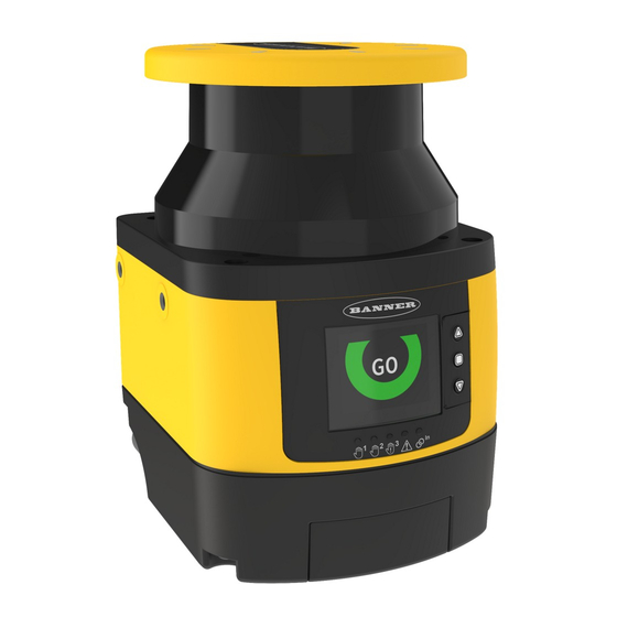
2 Product Overview
2.1 Models
Details the different SX Series Safety Laser Scanner models and their specifications.
2.3 Appropriate Applications and Limitations
Outlines suitable applications and crucial limitations for safe and effective scanner use.
2.8 Laser Safety (Class 1)
Explains the Class 1 laser safety classification and safe usage guidelines.
2.9 Software Overview
Introduces the SX scanner configuration software and its advantages.
2.9.2 Safety and Warning Zones
Describes the configuration of Safety and Warning Zones within the software.
3 Install Your Scanner
3.1 Safety Zone (SZ) and Warning Zone (WZ) Considerations
Key considerations for defining and implementing Safety and Warning Zones for protection.
3.2 Mechanical Installation Considerations
Factors influencing the physical mounting and installation of the scanner.
3.4 Minimum Safety (Separation) Distance for Stationary Applications
Details how to calculate the minimum safe distance for stationary installations.
3.5 Minimum Safety (Separation) Distance Formula
Provides the formulas and factors for calculating the minimum safety distance.
3.9 Mobile Applications
Covers specific considerations for installing the scanner on mobile equipment.
3.9.2 Minimum Distance D (Safety Zone Length) for Mobile Applications
Explains the calculation of safety zone length for mobile vehicle applications.
4 Electrical Connections
4.2 Initial Electrical Connections
Steps for making the initial power and system connections to the scanner.
4.3 Electrical Connections to the Guarded Machine
Procedures for connecting the scanner to the machine's control system.
4.3.1 Connecting the OSSD Outputs
Detailed instructions on wiring the Output Signal Switching Device (OSSD) outputs correctly.
4.4 Wiring Diagrams
Provides visual schematics for various machine interface connections.
4.4.1 Machine Interface Connections for the Stand-alone Models
Wiring diagram for stand-alone SX scanner models.
5 Initial Checkout
5.1 Apply Initial Power and Configure the SX Scanner System
Steps for applying power and performing initial scanner configuration.
5.2 Verify the Optical Field (Initial Verification)
Procedure to verify the scanner's detection field and status indicators.
5.3 Perform a Trip Test
Critical test to verify the functionality of Safety and Warning Zones.
6 Configuration Instructions
6.1 System Configuration Settings
Overview of essential settings for configuring the SX scanner system.
6.1.1 Response Time and Scan Cycle Setting
How to set the scanner's response time and scan cycle parameters.
6.1.2 Automatic or Manual Start/Restart
Configuration options for automatic versus manual system restart.
6.6 Using the Software
Guidance on operating the SX scanner configuration software.
6.6.1 Output Configuration
How to configure the scanner's output signals and their functions.
6.6.2 Zone Set Configuration
Detailed steps for creating and managing Safety and Warning Zones using zone sets.
6.6.4 Detection Configuration
Setting parameters like resolution, scans, and dust filter level for detection.
6.6.5 Create or Edit Safety and Warning Zones
Using software tools to draw and modify safety and warning zone shapes.
6.6.10 Connect a Scanner to a PC (Discover the Scanner)
Steps for connecting the scanner to a PC for configuration and discovery.
6.6.13 Monitor the Scanner
How to use the software's monitoring function to check scanner status and zones.
7 Operating Instructions
7.1 Status Indicators
Explains the meaning of the scanner's LEDs and display indicators.
7.3 Resetting the System
How to reset the scanner using an external switch or internal functions.
8 Checkout Procedures
8.1 Periodic Checkout Requirements
Outlines the schedule and requirements for system checkouts.
8.3 Perform a Commissioning Checkout
Critical procedure to verify installation and system operation.
8.4 Daily Checkout Procedure
Routine checks to be performed daily or at shift changes.
9 Troubleshooting
9.1 Initial Troubleshooting Steps
General steps to follow when encountering an error with the scanner.
9.2 Troubleshooting Lockout Conditions
Information on diagnosing and recovering from lockout conditions.
9.4 Diagnostic Notes, Warnings, and Errors
A comprehensive list of fault codes, device status, and OSSD status.
10 Accessories
10.1 Cordsets
Lists available cordsets for connecting the scanner to power and networks.
10.2 Brackets
Describes mounting brackets for scanner installation and adjustment.
10.4 Universal (Input) Safety Modules
Details compatible safety modules for system integration.
11 Product Support and Maintenance
11.1 Update the Firmware
Steps for updating the scanner's firmware to the latest version.
11.3 Cleaning the Window and Scatter Screen
Proper methods for cleaning the scanner's optical components.
11.4 Window Replacement
Procedure for replacing the scanner's optical window assembly.
11.4.2 Calibrate a New Window
Steps to calibrate the scanner after a new window replacement.
11.5 Fast Replacement in a System with a Memory Device
Procedures for quickly replacing scanner components using memory devices.
11.5.2 Fast Replacement of the Master Scanner
Procedure for rapidly replacing a master scanner unit.
12 Standards and Regulations
12.1 Applicable U.S. Standards
Lists relevant U.S. standards for machinery safety and design.
12.3 International/European Standards
Lists relevant international and European standards for machinery safety.
Table of Contents
Save PDF
Print
Rename the bookmark
Delete bookmark?
Delete from my manuals?
Login
Sign In
OR
Sign in with Facebook
Sign in with Google
Upload manual
Upload from disk
Upload from URL
Need help?
Do you have a question about the SX5-M10 and is the answer not in the manual?
Questions and answers