
Subscribe to Our Youtube Channel
Related Manuals for Bartell Global SPE DG250-II


Summary of Contents for Bartell Global SPE DG250-II
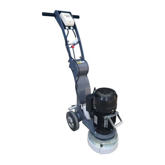
- Page 1 USER MANUAL DG250-II Floor Grinder Important!! Before operating the machine, please read this manual, and retain it for future reference.
-
Page 2: Table Of Contents
Contents Safety Precautions ................2 Introduction & description .............. 4 Technical data ................. 5 Operation Instructions ..............5 Troubleshooting ................9 Maintenance .................. 11 Exploded View ................12 PARTS LIST ..................13 This machine is designed to operate with the wheels in contact with the floor at all times. -
Page 3: Safety Precautions
Safety Precautions The Floor Grinder has been designed to minimize noise and vibration levels and to Provide maximum operator safety. However, incorrect use of the grinder may cause serious injury and therefore the following precautions must be taken: 1. Read and understand the instructions on the machine. Different models may have different parts and controls. - Page 4 13. Repairs should be performed by qualified persons only. 14. Ensure parts have stopped moving and disconnect power or spark plug when servicing or changing wheels or accessories. 15. Never operate machine in rain or heavy moisture. 16. Do not operate DG250-II with any covers or doors removed or open. 17.
-
Page 5: Introduction & Description
Introduction & description This manual is intended to provide operation and service information necessary for the safe and efficient use of the Floor Grinder. Operating or servicing the unit other than in accordance with the instructions given may subject the machine to conditions beyond its capability, which may result in machine failure or personal injury. -
Page 6: Technical Data
Technical data Motor HP Motor KW Rating 2.2kw Motor RPM 1410rpm Unit weight 67KG Plate type Standard 250mm plate or Cub Shoe Plate Bolt Types M12x25 Countersunk socket head Main Construction Powder Coated Steel Ensure all re-tipped and new grinding plates are properly balanced. Operation Instructions The floor grinder is designed to be used either wet or dry. - Page 7 Start the motor by pressing the black switch on the starter box. Lower the grinding plate and commence grinding. Stop the Grinder De-press the red stop button on the starter box. Note: By turning and pushing the handles, you can fix vertical grinding position. ...
- Page 8 9. If no power is available within the specified distance, have a qualified person install a suitable power outlet closer to your work. Alternatively use 4 mm2 cable for up t0 50 meters. 10. Connect a suitable dust extractor to the machine via a 50mm flexible hose. The machine is designed to take the standard GSA250 hose ends to make connection of dust extractors easy and hassle free.
- Page 9 20. All electrical maintenance and repairs to be carried out by qualified persons only. 21. CAUTION-Line terminals may be alive when main switch is in the off position. Disconnect all power at source before performing any maintenance or repairs. 22. WARNING-DO NOT operates the machine with any electrical panels open. 23.
-
Page 10: Troubleshooting
Troubleshooting SYMPTOM POSSIBLE CAUSE SOLUTION Machine doesn’t 1. No power is available at Check and confirm the power start/ run cable end; cable is available; 2. Machine is trying to start Clear a patch with scraper on glue or other sticky and grind into the glue a substance;... - Page 11 Grinder runs for 5- The current allow screw is not Adjust the current screw to 15 seconds, then adjusted properly the right position stops Extension cable too long and/or Get electrician to check not made from heavy enough extension lead compatibility cable Grinder runs but...
-
Page 12: Maintenance
Maintenance Daily cleaning: The motor in use should always be kept clean. No water drops, cotton etc should be allowed to get into the interior of the motors. Check on load current: While the motor is in operation, constant care should ... -
Page 13: Exploded View
Exploded View... -
Page 14: Parts List
PARTS LIST Item No. Part No. Description 100663 Main Disc 100279 Hexagon Socket Countersunk Screw 100664 Dowel Disc 100272 Flex Coupling 100253 Spring Lock Washers 100275 Hexagon Nut 100274 Hexagon Head Bolts 100266 Big Plain Washers 100276 Driving Sleeve 100277 Hexagon Head Bolts 100210 Hexagon Nut M12... - Page 15 100086 Spring washer 8-6/2 100268 Hexagon Head Bolts 100066 Cable Tie-in 100267 Pipe Joint 100222 Flexible Conduit L=480 100263 Big Clip 100222 Flexible Conduit L=245 100264 Small Clip 100249 Crossover Coupling 100249 Crossover Coupling 100666 Frame Body Part 100245 Inner Hexagon Spanner 100307 Flat Washer 12 100667...
- Page 16 100672 Plain Washers 100673 HEX. Lock nut M4 100674 Lock twist spring (left/right) 100675 Positioning clamping claw buckle Adjustable handle M10 ×25 100676 100252 Hexagon Socket Button head screws 100251 Wheel Adjustable handle M10 ×25 100250 100246 Quick Joint 100247 O-Ring 100678 Eccentric Shaft...
Need help?
Do you have a question about the SPE DG250-II and is the answer not in the manual?
Questions and answers