Subscribe to Our Youtube Channel
Summary of Contents for BIEMMEDUE JUMBO 400
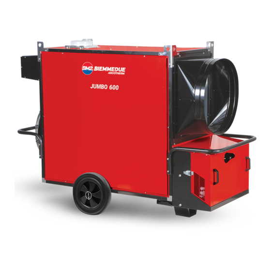
- Page 1 INSTRUCTIONS MANUAL MANUEL D'INSTRUCTIONS SPACE HEATER GENERATEUR D'AIR CHAUD JUMBO 400 - JUMBO 600 - JUMBO 800 L-L 267.00-BM 1 / 16...
- Page 2 CONTROL BOARD - SCHÉMA DE FONCTIONNEMENT HOT AIR OUTFLOW HOISTING BRACKETS SORTIE AIR CHAUD ÉTRIERS DE LEVAGE CHIMNEY SUPPORT/HANDLE CHEMINEE SUPPORT/POIGNEE COOLING FAN WHEEL VENTILATEUR REFROIDISSEMENT ROUE COMBUSTION CHAMBER 10 BURNER BOX CHAMBRE DE COMBUSTION BOÎTIER BRÛLEUR BURNER 11 BUFFER BRULEUR PARE-CHOCS THERMOSTATS L2 BOX...
- Page 3 CONTROL PANEL - TABLEAU DE COMMANDE HEATING-VENTILATION SWITCH TEMPERATURE CONTROLLER INTERRUPTEUR CHAUFFAGE-VENTILATION THERMORÉGULATEUR VOLTAGE LAMP BURNER LIGHT TEMOIN TENSION VOYANT BRÛLEUR OVERHEAT THERMOSTATS CONTROL LAMP, L2 SAFETY THERMOSTAT RESET BUTTON, L2 TEMOIN THERMOSTATS DE SURCHAUFFE, L2 POUSSOIR DE RÉARMEMENT THERMOSTAT DE SÉCURITÉ, L2 ROOM THERMOSTAT PLUG m BURNER RESET BUTTON / LAMP PRISE THERMOSTAT D’AMBIANCE...
-
Page 4: General Advice
IMPORTANT Before using the space heater, carefully read all of the instructions and follow them scrupulously. The manufacturer cannot be held responsible for damage to persons and/or property caused by improper use of the equipment. This instruction manual is an integral part of the equipment and must therefore be stored carefully and passed on with the unit in the event of a change of ownership. -
Page 5: Installation Instructions
there are no obstacles or obstructions to the air suction and/or delivery ducts, such as sheets or covers on the equipment, walls or large objects near the heater. Warning This unit may not be used by persons (including children) with reduced physical, sensorial or mental capacities or with limited experience and familiarity unless they are under supervision or instructed on how to use the unit by the person responsible for its safety. - Page 6 Any room thermostat or other accessories (such as a timer) are electrical panel and insert the plug into the socket H on the connected to the system by connecting the electrical cable to the burner; thermostat plug (c): • Take the plug (c) out of the electrical panel, open the plug and remove the jumper between terminals 2 and 3.
- Page 7 through nipple. 4.7. FIRST START-UP AND COMBUSTION ADJUSTMENT • Close the burner cover; Warning The first start-up should always be carried out by a 4.5. CONNECTION TO FUEL SUPPLY specialised technician checking the correctness of the Warning combustion parameters. The heater must be installed, set up, and used in compliance with all applicable regulations.
- Page 8 Warning Reset the counter as follows: If the burner goes into safety stop (lamp m) push reset • Turn the heater’s main switch to position “0” (OFF) button (d) for 3 seconds to restart the heater. • Press button P on the temperature controller for at least 3 seconds: the word “PASS”...
-
Page 9: Maintenance
6. MAINTENANCE • Pipes, connectors and joints: Warning • Clean with a cloth. All of the operations described in this section must be • External body: performed by professionally qualified personnel only. • Clean with a cloth. • Air inlet/outlet: The following procedures must be done at regular intervals to •... -
Page 10: Troubleshooting
remove any deposited soot and combustion residues. the blocking signal following intervention by the burner's flame control box. Warning After any technical work, always check that the heater Warning works correctly. NEVER do more than two restarts in a row: unburned fuel can accumulate in the combustion chamber and suddenly flare up at the next restart. - Page 11 WIRING DIAGRAM - SCHEMA ELECTRIQUE 120V, 1 , 60Hz FAN MOTOR RELAIS DE RETARD ALLUMAGE MOTEUR VENTILATEUR ANTI-CONDENSATION RESISTANCE FAN THERMOSTAT (setting: 30°C) RÉSISTANCE ANTICONDENSATION THERMOSTAT VENTILATEUR (régulation: 30°C) TM FANS TELE-CONTACTOR FB FUSE TELERUPTEUR VENTILATEUR FUSIBLE RM FANS THERMAL RELAY POWER LAMP RELAIS THERMIQUE VENTILATEUR LAMPE TEMOIN MISE SOUS TENSION...
- Page 12 WIRING DIAGRAM - SCHEMA ELECTRIQUE 240V, 1 , 60Hz FAN MOTOR RELAIS DE RETARD ALLUMAGE MOTEUR VENTILATEUR ANTI-CONDENSATION RESISTANCE FAN THERMOSTAT (setting: 30°C) RÉSISTANCE ANTICONDENSATION THERMOSTAT VENTILATEUR (régulation: 30°C) TM FANS TELE-CONTACTOR FB FUSE TELERUPTEUR VENTILATEUR FUSIBLE RM FANS THERMAL RELAY POWER LAMP RELAIS THERMIQUE VENTILATEUR LAMPE TEMOIN MISE SOUS TENSION...
-
Page 13: Technical Specifications
TECHNICAL SPECIFICATIONS JUMBO 400 Nominal heat input [BTU/h] 400,000 Heat input [BTU/h] 396,730 Fuel consumption [USgal/h] 2.83 Burner Model RIELLO R40-F10TC Burner Nozzle [USgal/h] Delavan 2.00 - 60° B Combustion head setting [N°] Pump pressure [psi] Burner air setting [N°]... - Page 14 TECHNICAL SPECIFICATIONS JUMBO 600 Nominal heat input [BTU/h] 600,000 Heat input [BTU/h] 593,367 Fuel consumption [USgal/h] 4.23 Burner Model RIELLO R40-F15TC Burner Nozzle [USgal/h] Danfoss 3.00 - 60° S Combustion head setting [N°] Pump pressure [psi] Burner air setting [N°] Air flow [cfm] 7,063...
- Page 15 TECHNICAL SPECIFICATIONS JUMBO 800 Nominal heat input [BTU/h] 800,000 Heat input [BTU/h] 784,030 Fuel consumption [USgal/h] 5.59 Burner Model RIELLO R40-F20TC Burner Nozzle [USgal/h] Danfoss 4.50 - 60° S Combustion head setting [N°] I Stage [psi] Pump pressure II Stage [psi] I Stage [N°]...
- Page 16 NOTICE DE MONTAGE DU PIED/DE LA POIGNEE - FOOT / HANDLE ASSEMBLY INSTRUCTION BIEMMEDUE S.p.A. Via Industria,12 - 12062 - Cherasco (CN) - Italy Tel. +39 0172 486111 - Fax +39 0172 488270 www. biemmedue.com - bm2@biemmedue.com L-L 267.00-BM 16 / 16...


Need help?
Do you have a question about the JUMBO 400 and is the answer not in the manual?
Questions and answers