
Subscribe to Our Youtube Channel
Related Manuals for ATEN VanCryst VE1801AEUT


Summary of Contents for ATEN VanCryst VE1801AEUT
- Page 1 ATEN VanCryst™ VE1801AEUT / VE1801AUST HDMI HDBaseT Transmi er with EU / US Wall Plate / PoH User Manual...
-
Page 2: Compliance Statements
VE1801AEUT / VE1801AUST User Manual Compliance Statements FEDERAL COMMUNICATIONS COMMISSION INTERFERENCE STATEMENT This equipment has been tested and found to comply with the limits for a Class A digital device, pursuant to Part 15 of the FCC Rules. These limits are designed to provide reasonable protection against harmful interference when the equipment is operated in a commercial environment. - Page 3 VE1801AEUT / VE1801AUST User Manual Industry Canada Statement This Class A digital apparatus complies with Canadian ICES-003. HDMI Trademark Statement The terms HDMI, HDMI High-Definition Multimedia Interface, and the HDMI Logo are trademarks or registered trademarks of HDMI Licensing Administrator, Inc. RoHS This product is RoHS compliant.
-
Page 4: About This Manual
Read this manual thoroughly and follow the installation and operation procedures carefully to prevent any damage to the unit or any connected devices. ATEN regularly updates its product documentation for new features and fixes. For an up-to-date VE1801AEUT / VE1801AUST documentation, visit... -
Page 5: Conventions
VE1801AEUT / VE1801AUST User Manual Conventions This manual uses the following conventions: Indicates text that you should key in. Monospaced Indicates keys you should press. For example, [Enter] means to press the Enter key. If keys need to be chorded, they appear together in the same bracket with a plus sign between them: [Ctrl+Alt]. -
Page 6: Package Contents
VE1801AEUT / VE1801AUST User Manual Package Contents VE1801AEUT 1 VE1801AEUT HDMI HDBaseT-Lite Transmitter with EU Wall Plate / PoH 1 5-pin terminal block 1 rubber pad set (4 pcs) 1 faceplate 2 pan head screws 4 PF screws 1 power adapter 1 user instructions* VE1801AUST 1 VE1801AUST HDMI HDBaseT-Lite Transmitter with US Wall Plate / PoH... -
Page 7: Product Information
For information about all ATEN products and how they can help you connect without limits, visit ATEN on the Web or contact an ATEN Authorized Reseller. Visit ATEN on the Web for a list of locations and telephone numbers: International http://www.aten.com... -
Page 8: User Notice
VE1801AEUT / VE1801AUST User Manual User Notice All information, documentation, and specifications contained in this manual are subject to change without prior notification by the manufacturer. The manufacturer makes no representations or warranties, either expressed or implied, with respect to the contents hereof and specifically disclaims any warranties as to merchantability or fitness for any particular purpose. -
Page 9: Table Of Contents
Considerations ......... . . 3 Compatible ATEN Video Extenders ......3 Components . - Page 10 VE1801AEUT / VE1801AUST User Manual International ..........21 North America .
-
Page 11: Introduction
Overview The ATEN VE1801AEUT / VE1801AUST HDMI HDBaseT-Lite transmitter delivers 4K signals up to 40 m over a single Cat 5e/6/6a or ATEN 2L-2910 Cat 6 cable, ensuring users to stabilize HDMI signal transmission with support of 3D, Deep color and embedded HD lossless audio formats. During high-quality... -
Page 12: Features
VE1801AEUT / VE1801AUST User Manual Features Extends HDMI signals with superior video quality over a single Cat 5e/6/ 6a cable or ATEN 2L-2910 Cat 6 cable 4K up to 40 m 1080p up to 70 m Built-in PoH (Power over HDBaseT) function – the VE1801AEUT / VE1801AUST receives power supply from the HDBaseT output port ... -
Page 13: Planning The Installation
1 HDMI source device 1 Cat 5e/6/6a or ATEN 2L-2910 Cat 6 cable Considerations To ensure video quality, ATEN recommends using a Cat 5e/6/6a cable. Note: ATEN recommends using an ATEN 2L-2910 Cat 6 cable for best results. -
Page 14: Components
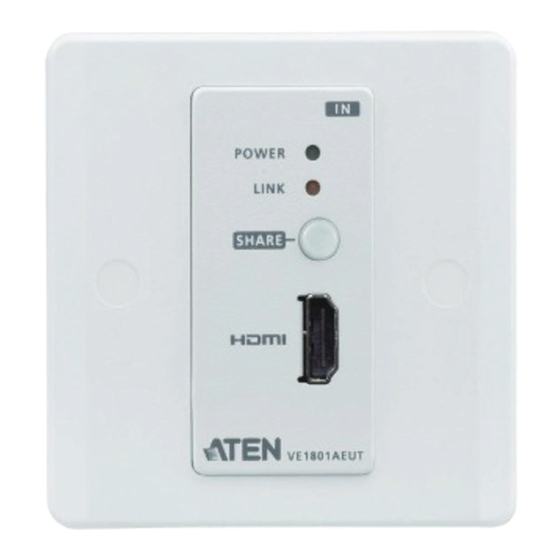
VE1801AEUT / VE1801AUST User Manual Components Front View VE1801AEUT VE1801AUST No. LED Indication Description power LED Lights green The unit is receiving power. link LED Lights orange The transmission to the receiver is stable. Blinks orange The transmission to the receiver is unstable. share pushbutton Press this pushbutton to share source with the VP1421. -
Page 15: Rear View
VE1801AEUT / VE1801AUST using serial commands. RS-232 for firmware This switch is reserved for ATEN Technical upgrade switch Support. If you would like to do a firmware upgrade yourself, please contact your dealer. - Page 16 VE1801AEUT / VE1801AUST User Manual No. Component Description RS-232 terminal (Tx & Rx) Connects to the 5-pin terminal block for the following purposes. DO contact closure terminal For remotely control on the connected device (DO for share pushbutton) via RS-232 serial commands, connect the RS- +5V DC power-in terminal 232 terminal (Tx &...
-
Page 17: Top View
Chapter 1. Introduction Top View VE1801AEUT VE1801AUST No. Component Description HDBaseT out port with Connects to the HDBaseT input port on a compatible PoH PD power receiving ATEN HDBaseT receiver via an RJ-45 cable. - Page 18 VE1801AEUT / VE1801AUST User Manual This Page Intentionally Left Blank...
-
Page 19: Hardware Setup
Chapter 2 Hardware Setup 1. Please review the safety information regarding the placement of this device in Safety Instructions, page 19. 2. Do not power on the VE1801AEUT / VE1801AUST until all the necessary hardware is connected. Mounting the VE1801AEUT / VE1801AUST Unit VE1801AEUT / VE1801AUST is designed to be installed in a wall, ground, or a table. -
Page 20: Ve1801Aeut Wall Mount
VE1801AEUT / VE1801AUST User Manual VE1801AEUT Wall Mount 1. Secure the faceplate to the unit using the 4 PF screws provided. 2. Secure the unit to the installation site using the 2 pan head screws provided, and attach the rubber pads onto the pan head screws. This installation site can be a wall, ground, or table. -
Page 21: Ve1801Aust Wall Mount
Chapter 2. Hardware Setup VE1801AUST Wall Mount 1. Secure the unit to a wall box or mud ring using the flat head screws provided. Note: The wall box and mud ring are not provided in the package. mud ring wall box 2. -
Page 22: Connecting The Ve1801Aeut / Ve1801Aust Unit
VE1801AEUT / VE1801AUST User Manual Connecting the VE1801AEUT / VE1801AUST Unit Follow the steps below to connect the VE1801AEUT / VE1801AUST to a source, a compatible ATEN HDBaseT receiver, and other controls as required. VE1801AUST Front View Rear View Top View... -
Page 23: Terminal Block Connection
Chapter 2. Hardware Setup 4. Connect the HDMI output port on the VE802R to a display device using an HDMI cable. 5. (Optional) Connect the RS-232 interface of your computer or control system to the RS-232 and ground terminals on the unit using the 5-pin terminal block provided. -
Page 24: Power Supply Information
VE1801AEUT / VE1801AUST User Manual Power Supply Information (Optional) If you wish to use power adapter for power, follow the steps below. 1. Cut the connector end of the power adapter. 2. Strip 5 mm (0.5cm) off the insulation cover of the power adapter cable to expose two wires: a +5V wire and a GND (grounding) wire. -
Page 25: Rs-232 Channel Transmission
Chapter 2. Hardware Setup RS-232 Channel Transmission You can manage the connected devices via RS-232 serial devices, such as computers or bar code scanners. The RS-232 signal transmission flow can be illustrated as follows: Note: The unit used in the diagram below is VE1801AUST, the procedure for connecting VE1801AEUT is identical. - Page 26 VE1801AEUT / VE1801AUST User Manual This Page Intentionally Left Blank...
-
Page 27: Operation
Chapter 3 Operation RS-232 Serial Transmission The RS-232 Serial Transmission allows you to bypass serial data to remotely control the device connected to the VE1801AEUT / VE1801AUST using serial commands. Bypass RS-232 serial data is bypassed from the controller PC or Pad to other connected devices. -
Page 28: Connecting The Unit With Vp1421
VE1801AEUT / VE1801AUST User Manual Connecting the Unit with VP1421 To share source device to the VP1421, follow the steps below. For more information on how to connect the VP1421, see VP1421-VP1421 user manual. Note: The unit used in the diagram below is VE1801AUST, the procedure for connecting VE1801AEUT is identical. -
Page 29: Appendix
Appendix Safety Instructions General This product is for indoor use only. Read all of these instructions. Save them for future reference. Follow all warnings and instructions marked on the device. Do not place the device on any unstable surface (cart, stand, table, etc.). If the device falls, serious damage will result. - Page 30 VE1801AEUT / VE1801AUST User Manual If the following conditions occur, unplug the device from the wall outlet and bring it to qualified service personnel for repair. The power cord or plug has become damaged or frayed. Liquid has been spilled into the device. ...
-
Page 31: Technical Support
Support Documentation Software Updates Telephone Support 1-888-999-ATEN ext 4988 1-949-428-1111 When you contact us, please have the following information ready beforehand: Product model number, serial number, and date of purchase Your computer configuration, including operating system, revision level, expansion cards, and software ... -
Page 32: Specifications
HDCP 2.2 Compatible Consumer Electronics Control (CEC) Max. Resolutions / HDMI: Distances Up to 4k @35m (Cat 5e/6) / 40m (Cat 6a/ATEN 2L-2910 Cat6) Up to 1080p @60m (Cat 5e/6) / 70m (Cat 6a/ATEN 2L- 2910 Cat6) 4k supported: ... - Page 33 Appendix Function VE1801AEUT VE1801AUST Connectors 1 x Terminal Block, 5 Pole, +5V / GND (Green) 1 x RJ-45 Female (PoH) Consumption DC 5V;3.26W;15BTU PoH;4W;19BTU Environmental Operating Temperature 0 - 40°C Storage Temperature -20 - 60°C Humidity 0 x 80% RH, Non-Condensing Physical Properties Housing Metal...
- Page 34 VE1801AEUT / VE1801AUST User Manual This Page Intentionally Left Blank This page is for CAD Drawings...
- Page 35 Appendix This page is for CAD Drawings...
- Page 36 VE1801AEUT / VE1801AUST User Manual This page is for CAD Drawings...
- Page 37 Appendix This page is for CAD Drawings...
- Page 38 VE1801AEUT / VE1801AUST User Manual This page is for CAD Drawings...
- Page 39 Appendix This page is for CAD Drawings...
- Page 40 VE1801AEUT / VE1801AUST User Manual This page is for CAD Drawings...
- Page 41 Appendix This page is for CAD Drawings...
-
Page 42: Limited Warranty
© Copyright 2021 ATEN® International Co., Ltd. Released: 2021-04-29 ATEN and the ATEN logo are registered trademarks of ATEN International Co., Ltd. All rights reserved. All other brand names and trademarks are the registered property of their respective owners. -
Page 43: Template Printing
Appendix Template Printing Please use 1:1 ratios when printing. We also recommend using A4 sized paper or larger. After printing, please measure the print so that the labeled measurement is correct.
Need help?
Do you have a question about the VanCryst VE1801AEUT and is the answer not in the manual?
Questions and answers