Table of Contents
Advertisement
Quick Links
Manual content is subject to change.
Visit www.midlandmfg.com for latest manual revision and revision history.
A-520/A-522/A-522A Series
4" Bottom Outlet Ball Valve
Installation, Operation & Maintenance (IOM) Manual
P/N: A-520/A-522/A-522A, Rev. 3.0
Issue Date: April 01, 2021 Supersedes: A-520/522,
Rev. 2.2
Advertisement
Table of Contents

Related Manuals for Midland A-520 Series


Summary of Contents for Midland A-520 Series
- Page 1 P/N: A-520/A-522/A-522A, Rev. 3.0 Issue Date: April 01, 2021 Supersedes: A-520/522, Rev. 2.2 A-520/A-522/A-522A Series 4" Bottom Outlet Ball Valve Installation, Operation & Maintenance (IOM) Manual Manual content is subject to change. Visit www.midlandmfg.com for latest manual revision and revision history.
-
Page 2: Table Of Contents
Manual content is subject to change. Visit midlandmfg.com for latest IOM revision and revision history. Table of Contents Regulations and Safety Requirements ................... 3 Regulations ..........................3 Safety Warnings and Precautions................... 3 Introduction ............................ 4 Component Identification and Parts Listings ................4 Steam-Jacket Configurations .................... -
Page 3: Regulations And Safety Requirements
1 Regulations and Safety Requirements Regulations Midland bottom-outlet ball valves are used in contact with a variety of products, many of which are hazardous materials and could cause serious injury or damage if mishandled. The acceptance and transportation of products are regulated by the DOT and AAR in the U.S.A., and in Canada by CTC and Transport Canada. -
Page 4: Introduction
Manual content is subject to change. Visit midlandmfg.com for latest IOM revision and revision history. 2 Introduction The A-520, A-522, and A-522A 4” Bottom-Outlet Ball Valves offer greater resistance to abrasion. They also reduce the chance of leakage caused by particle contamination in harsh applications. Low and standard profiles available •... - Page 5 Manual content is subject to change. Visit midlandmfg.com for latest IOM revision and revision history. A-520-C2-CS A-520-C2-MO ITEM DESCRIPTION PART NO. MATERIAL PART NO. MATERIAL 520-112-CS STEEL 520-112-MO STAINLESS STEEL STEM 520-2-SS STAINLESS STEEL 520-2-SS STAINLESS STEEL BALL 520-30-MO STAINLESS STEEL 520-30-MO STAINLESS STEEL BODY...
- Page 6 Manual content is subject to change. Visit midlandmfg.com for latest IOM revision and revision history. A-522-C1-CS A-522-C1-MO ITEM DESCRIPTION PART NO. MATERIAL PART NO. MATERIAL 520-112-CS STEEL 520-112-MO STAINLESS STEEL STEM 520-2-SS STAINLESS STEEL 520-2-SS STAINLESS STEEL BALL 520-3-MO STAINLESS STEEL 520-3-MO STAINLESS STEEL BODY...
- Page 7 Manual content is subject to change. Visit midlandmfg.com for latest IOM revision and revision history. A-522-C2-CS A-522-C2-MO ITEM DESCRIPTION PART NO. MATERIAL PART NO. MATERIAL 520-112-CS STEEL 520-112-MO STAINLESS STEEL STEM 520-2-SS STAINLESS STEEL 520-2-SS STAINLESS STEEL BALL 520-30-MO STAINLESS STEEL 520-30-MO STAINLESS STEEL BODY...
- Page 8 Manual content is subject to change. Visit midlandmfg.com for latest IOM revision and revision history. A-522A-C2-CS A-522A-C2-MO ITEM DESCRIPTION PART NO. MATERIAL PART NO. MATERIAL 520-113-CS STEEL 520-113-MO STAINLESS STEEL STEM 520-2-SS STAINLESS STEEL 520-2-SS STAINLESS STEEL BALL 520-30-MO STAINLESS STEEL 520-30-MO STAINLESS STEEL BODY...
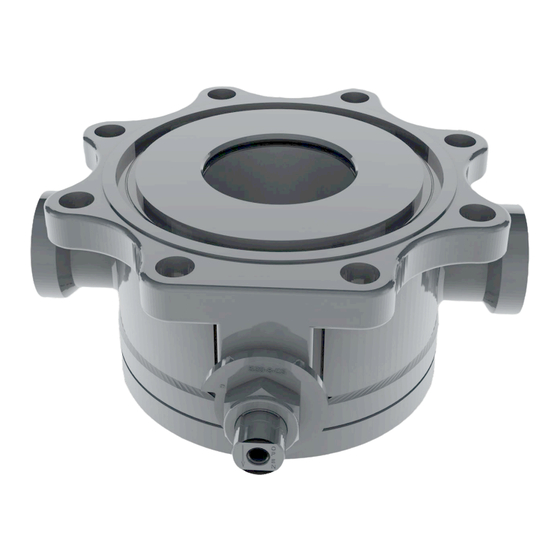
- Page 9 Manual content is subject to change. Visit midlandmfg.com for latest IOM revision and revision history. Figure 2-1 A-52X Component Identification Figure 2-2 A-522A Component Identification A-520/A-522/A-522A, Rev. 3.0 Page 9 of 28...
-
Page 10: Steam-Jacket Configurations
Manual content is subject to change. Visit midlandmfg.com for latest IOM revision and revision history. Steam-Jacket Configurations Note that only the legacy A-522 models have a steam jacket configuration; the updated A-522A does not have this configuration. Figure 2-3 A-520-SJ Valve w/Steam-Jacket Configuration Figure 2-4 A-522-SJ w/Steam-Jacket Configuration A-520/A-522/A-522A, Rev. - Page 11 Manual content is subject to change. Visit midlandmfg.com for latest IOM revision and revision history. NOTICE: Shown for information only. For specific details on steam jackets (i.e., part numbers and dimensions), contact Midland Customer Service. A-520/A-522/A-522A, Rev. 3.0 Page 11 of 28...
-
Page 12: Valve Installation
Manual content is subject to change. Visit midlandmfg.com for latest IOM revision and revision history. 3 Valve Installation Keep the new valve in its original shipping container. This will ensure it remains Gasket-Sealing Surfaces clean and will protect the gasket groove and ball from nicks and damage. Prior to installation, ensure that the valve remains clean and the gasket-sealing surfaces are not damaged. - Page 13 Manual content is subject to change. Visit midlandmfg.com for latest IOM revision and revision history. NOTICE: The ball valve should be installed in the “open” position so that the ball surfaces are protected during the following steps. Figure 3-2 Ball Valve in Open Position Raise the valve up to the tank-car mounting flange surface.
-
Page 14: Leak Inspection
Manual content is subject to change. Visit midlandmfg.com for latest IOM revision and revision history. Leak Inspection Test all newly installed valves to conform to car-owner specifications. No leaks should be present. WARNING: Valve Leakage. Improper flange-tongue seating in the valve groove, loose bolts and damaged gaskets may result in leaks at the valve-mounting joint. -
Page 15: Valve Qualification
Manual content is subject to change. Visit midlandmfg.com for latest IOM revision and revision history. 4 Valve Qualification Follow these instructions and guidelines for assessing the condition of a leaking ball valve prior to rebuilding it. NOTICE: To ensure best practices and consistency of your qualification procedure, gaskets, O-rings, valve seats and wire seals should always be replaced. - Page 16 Manual content is subject to change. Visit midlandmfg.com for latest IOM revision and revision history. Remove the eight (8) socket hex-head cap screws (item 9) from the valve cap (Item 1). CAUTION: Valve Damage. Avoid using forceful tools on seal-support surfaces when removing ball seals and stem packing, or damage may result.
- Page 17 Manual content is subject to change. Visit midlandmfg.com for latest IOM revision and revision history. Remove the stop plate (item 8) and then carefully press the valve stem (item 2) into the body (item 4) cavity and remove it. TIP: The use of a brass or plastic hammer may be required to overcome the resistance of the compressed stem packing.
-
Page 18: Component Inspection
NOTICE: Procedures may not cover all conditions encountered in the field. Therefore, it is the responsibility of the repair agency to obtain approval from Midland for inspection, evaluation, repair and maintenance procedures not covered herein. Evaluation of critical component metal surfaces of the valves after cleaning, inspection, specialized testing performed by agencies other are the responsibility of the repair facility. -
Page 19: Special Inspection Considerations
Previous procedures may not cover all conditions encountered in the field. Therefore, it is the responsibility of the repair agency to contact an authorized Midland technical representative for recommendations regarding unusual valve conditions or repair circumstances that may be encountered. -
Page 20: Valve Assembly And Testing Requirements
Manual content is subject to change. Visit midlandmfg.com for latest IOM revision and revision history. Valve Assembly and Testing Requirements NOTICE: Valve assembly and testing is to be done at a recommended temperature of 70°F. The acceptable temperature range for valve assembly is 40°F to 100°F. NOTICE: When re-assembling it is important to notice which valve it is. - Page 21 Manual content is subject to change. Visit midlandmfg.com for latest IOM revision and revision history. Install the thrust washer (item 12) onto the valve stem (item 2). TIP: Apply a thin layer of grease (such as Panef Petrolatum) to smooth section of the stem (item 2).
- Page 22 Manual content is subject to change. Visit midlandmfg.com for latest IOM revision and revision history. Install the stop plate (item 8). When oriented as shown, and with the valve “Open” (as recommended to prevent ball-handling damage), the stop plate part number etching will be visible and there should be an etched “O” nearest the limiting pin.
- Page 23 Manual content is subject to change. Visit midlandmfg.com for latest IOM revision and revision history. Wipe down one of the body ball seals (item 10) and then place it into the bottom seat of the valve body (item 4), flat side donwards. Be very careful to avoid damaging the seat during installation.
- Page 24 Manual content is subject to change. Visit midlandmfg.com for latest IOM revision and revision history. Wipe down the second ball seal (item 10) and then place is into the seat of the cap plate (item 1) with the flat side downward. Be very careful to avoid damaging the seal during installation.
- Page 25 Manual content is subject to change. Visit midlandmfg.com for latest IOM revision and revision history. Install four (4) extra 5/8”-11 UNC 2A 1-3/4” long cap screws (item 9) without Locktite. TIP: Use a 5/8” wrench to tighten the cap screws (item 9). Figure 4-31 Install Cap Screws Tighten the eight (8) cap screws (item 9) in a crisscross sequence until the cap plate contacts the valve body (item 4).
- Page 26 Manual content is subject to change. Visit midlandmfg.com for latest IOM revision and revision history. Place the vavle in a suitable test fixture and pour water into the valve outlet port so that it covers the sealing area. Figure 4-34 Immerse Seal for Leak Test Apply air pressure to the valve at 300 psig.
-
Page 27: Routine Maintenance
Manual content is subject to change. Visit midlandmfg.com for latest IOM revision and revision history. 5 Routine Maintenance Leak Checking in the Field Because of the ball valve’s simplicity, the only maintenance procedure consists of checking the valve for leaks. If the valve is leaking from its outlet port, rebuild or replace it. - Page 28 © Copyright 2021, OPW. Printed in USA. © 2021 Delaware Capital Formation, Inc. All Rights Reserved.
Need help?
Do you have a question about the A-520 Series and is the answer not in the manual?
Questions and answers