
Subscribe to Our Youtube Channel
Related Manuals for Midland A-7200


Summary of Contents for Midland A-7200
- Page 1 P/N: A-7200/A-7300, Ver. 1.0 Issue Date: April 27, 2020 Top-Transfer Ball Valve A-7200/A-7240 and A-7300/A-7340 Installation, Operation & Maintenance (IOM) Manual...
-
Page 2: Table Of Contents
Valve Disassembly and Required Tools ................10 Component Inspection ......................13 Valve Assembly and Testing Requirements ................. 15 Valve Assembly and Testing Procedure ................16 Routine Maintenance ........................20 Leak Checking in the Field ....................20 A-7200/A-7300, Ver. 1.0 Page 2 of 21... -
Page 3: Regulations And Safety Requirements
Specifications are subject to change without notice. Midland valves are used in connection with a variety of products, many of which are hazardous materials and could cause serious injury or damage if mishandled. This valve should only be installed, operated and maintained by qualified personnel. -
Page 4: Introduction
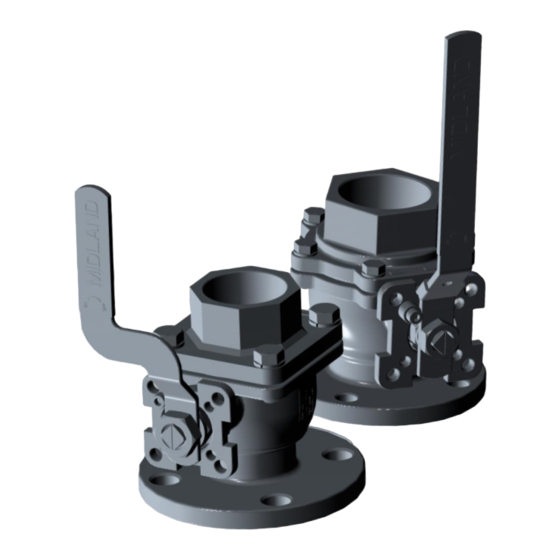
2 Introduction The A-7200 and A-7240 Series 2” Top-Transfer Ball Valve and A-7300 and A-7340 Series 3” Top-Transfer Ball Valve offer greater resistance to abrasion. The valve also reduces the chance of leakage caused by particle contamination in harsh applications. - Page 5 A-7200 (CARBON STEEL W/ STAINLESS STEEL TRIM) A-7240 (STAINLESS STEEL) ITEM DESCRIPTION MATERIAL PART NUMBER MATERIAL PART NUMBER END CAP CARBON STEEL 7200-1-CS 316 STAINLESS STEEL 7240-1-MO STEM STAINLESS STEEL 7200-2-SS STAINLESS STEEL 7200-2-SS BALL 316 STAINLESS STEEL 7200-3-SS 316 STAINLESS STEEL...
- Page 6 304 STAINLESS STEEL 7340-21-SS NAME PLATE STAINLESS STEEL 7200-22-SS STAINLESS STEEL 7240-22-SS DRIVE SCREW STAINLESS STEEL 763-11-SS STAINLESS STEEL 763-11-SS VALVE PART NO. ITEM 11, SEAL MATERIAL A-7300 7300-11-VTF VIRGIN PTFE A-7340 7300-11-VTF VIRGIN PTFE A-7200/A-7300, Ver. 1.0 Page 6 of 21...
-
Page 7: Torque And Bolt Size Table References
4 or 6 2” or 3” M 12 53 - 65 ft-lb Table 2-4 Wrench/Socket Bolt Size Size 5/8" 1-1/16" 3/4" 1-1/8" or M 26 M 22 M 32 M 12 M 19 A-7200/A-7300, Ver. 1.0 Page 7 of 21... -
Page 8: Valve Installation
If the valve is reconditioned, or retested, inspect the sealing surface to ensure it is free of nicks, gouges and burrs. Properly install a new mounting gasket (not provided by Midland). Start all four (4) hex nuts on the studs while lowering the valve into position or the valve will need to be lifted off the studs and the hex nuts started to give clearance. -
Page 9: Valve Operation Notes And Precautions
Rotate bar handle to operate valve open (figure Open Position on left) and close (figure on right). To ensure the valve is fully open, or closed, fully engage the handle to the pin stops. A-7200/A-7300, Ver. 1.0 Page 9 of 21... -
Page 10: Valve Qualification
Hold the valve securely by the flange for safety and rigidity during hardware removal. Figure 4-1 Remove the nut (item 17) from the stem (item 2) by turning it counterclockwise. Then remove the handle (item 18) and lockwasher (item 12). (Figure 4-2) Figure 4-2 A-7200/A-7300, Ver. 1.0 Page 10 of 21... - Page 11 (item 3). Lift the ball out of the body and set it on a padded surface. (Figure 4- Figure 4-5 Remove the packing nut (Item 17) from the valve stem (item 2) by turning it counterclockwise. (Figure 4-6) Figure 4-6 A-7200/A-7300, Ver. 1.0 Page 11 of 21...
- Page 12 (item 5) from the valve-stem bore. Avoid scratching or gouging the interior surfaces for the valve-stem bore. (Figure 4-9) Figure 4-9 Carefully remove the ball seal (item 11) from the inside-bottom of the valve body (item 4). (Figure 4-10) Figure 4-10 A-7200/A-7300, Ver. 1.0 Page 12 of 21...
-
Page 13: Component Inspection
Midland are the responsibility of the repair facility. Where numerical tolerances can be provided, the disposition of the internal integrity and surface quality of parts is under the jurisdiction of the repair facility and dependent on its experience and judgment. - Page 14 Critical Surfaces Figures 4-18 and 4-19 Valve End Cap Inspection 4.2.4.1 Check the valve end cap (item 1) and the ball-seal surfaces for signs of corrosion, cracks and scratches. No defects are allowed. A-7200/A-7300, Ver. 1.0 Page 14 of 21...
-
Page 15: Valve Assembly And Testing Requirements
D4.5 Test Gauge Standards and be date-tagged. 4.3.1.2 Valve Testing Procedure If your company has its own reassembly/test procedure, follow it. If it does not, the following procedure provides the essential guidelines. A-7200/A-7300, Ver. 1.0 Page 15 of 21... -
Page 16: Valve Assembly And Testing Procedure
(item 4), flat side downward. Be very careful to avoid damaging the seat during installation. (Figure 4-22) Figure 4-22 Install the thrust washer (item 19) onto the valve stem (item 2). (Figure 4-23) Figure 4-23 A-7200/A-7300, Ver. 1.0 Page 16 of 21... - Page 17 Install packing nut (item 17) and torque the packing nut according to Table 2-2 in Section 2.2. (Figure 4-27) 3/4”-10 UNC 23 - 28 ft-lb M 22 30 - 36 ft-lb Figure 4-27 A-7200/A-7300, Ver. 1.0 Page 17 of 21...
- Page 18 Tighten the four (4) cap screws (item 9) in a crisscross sequence. The bolts should be tightened evenly until the cap (item 1) is in contact with the body and should be torqued according to Table 2-3. M 12 53 - 65 ft-lb Figure 4-30 A-7200/A-7300, Ver. 1.0 Page 18 of 21...
- Page 19 Depressurize the valve body (item 4). Adjust the valve so that it is half open (approximately 45 degrees). Install a 2” or 3” test plug, size respective to A-7200 or A-7300 series. Apply air pressure to the valve at 300 psig for two minutes.
-
Page 20: Routine Maintenance
WARNING: Do not exceed the upper limit noted in Table 2-2 in Section 2.2 of torque when tightening the locknut (item 17). 3/4”-10 UNC 23 - 28 ft-lb M 22 30 - 36 ft-lb A-7200/A-7300, Ver. 1.0 Page 20 of 21... - Page 21 © Copyright 2016, OPW. Printed in USA. © 2016 Delaware Capital Formation, Inc. All Rights Reserved.
Need help?
Do you have a question about the A-7200 and is the answer not in the manual?
Questions and answers