Table of Contents
Advertisement
Part Number: A-22075/6, Rev. 1.1
Issue Date: July 25, 2016
Supersedes: A-22075/6, Rev. 1.0
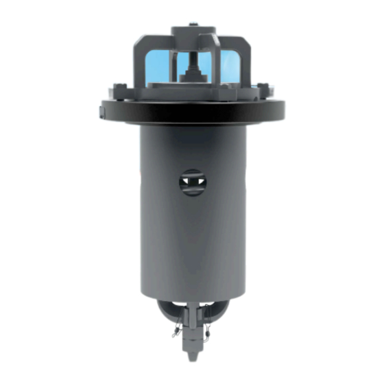
Internal-Style Pressure Relief Valve
A-22075 Series and A-22076 Series
Installation, Operation and Maintenance (IOM) Manual
7733 Gross Point Road • Skokie, IL 60077 • (847) 677-0333 • Fax (847) 677-0138 • www.midlandmfg.com
Advertisement
Table of Contents

Related Manuals for Midland A-22075 Series


Summary of Contents for Midland A-22075 Series
- Page 1 Issue Date: July 25, 2016 Supersedes: A-22075/6, Rev. 1.0 Internal-Style Pressure Relief Valve A-22075 Series and A-22076 Series Installation, Operation and Maintenance (IOM) Manual 7733 Gross Point Road • Skokie, IL 60077 • (847) 677-0333 • Fax (847) 677-0138 • www.midlandmfg.com...
-
Page 2: Table Of Contents
P/N: A-22075/6, Rev. 1.1 Page 2 of 45 Table of Contents Introduction .......................... 3 Technical Specifications ....................3 Valve Perspectives ......................5 Pre-Installation Regulations/Requirements ..............8 Valve Installation ....................... 10 Preliminary Considerations .................... 10 Procedure ........................10 Leak Inspection ......................12 Valve Operation Notes and Precautions ............... -
Page 3: Introduction
P/N: A-22075/6, Rev. 1.1 Page 3 of 45 Introduction The A-22075 Series and A-22076 Series Internal-Style Pressure Relief Valves are high-flow, corrosion- resistant devices designed for use with crude-oil and ethanol tank cars requiring high-flow pressure relief. High-quality steel construction •... - Page 4 P/N: A-22075/6, Rev. 1.1 Page 4 of 45 Figure 1-2 A-22075-PI and A-22076-PI Valve Dimensions...
-
Page 5: Valve Perspectives
P/N: A-22075/6, Rev. 1.1 Page 5 of 45 Valve Perspectives Figure 1-3 A-22075-PI/A-22076-PI Valve Exploded View... - Page 6 P/N: A-22075/6, Rev. 1.1 Page 6 of 45 Item Qty. Part Name Top Guide with Insert Valve Stem Assembly Retainer Valve Body PRV Spring Follower Insert Locknut O-ring (2-431) O-ring (2-351) Hex Nut Hex-Head Cap Screw Hex-Head Cap Screw Name Plate Drive Screw Gasket Wire-Seal Kit...
- Page 7 P/N: A-22075/6, Rev. 1.1 Page 7 of 45 Item Qty. Part Name Top Guide with Insert Valve Stem Assembly Retainer Valve Body PRV Spring Follower Insert Locknut O-ring (2-431) O-ring (2-351) Hex Nut Hex-Head Cap Screw Hex-Head Cap Screw Name Plate Drive Screw Gasket Wire-Seal Kit...
-
Page 8: Pre-Installation Regulations/Requirements
1.3.1 Regulations Midland internal-style valves are used in contact with a variety of products, many of which are hazardous materials. The acceptance and transportation of products are regulated by the DOT and AAR in the U.S.A., and in Canada by CTC and Transport Canada. Regulations of other governmental bodies must be complied with for stationary and mobile applications. - Page 9 P/N: A-22075/6, Rev. 1.1 Page 9 of 45 1.3.3 Precautions for Mounted-Valve Repair When performing maintenance on a pressure relief valve that is mounted on a railcar, observe the following precautions: Wear protective clothing and equipment suitable for withstanding the materials to which you may •...
-
Page 10: Valve Installation
Preliminary Considerations 2.1.1 New valves are tested, adjusted and sealed at Midland. If a new valve has been left in its original packaging, is undamaged and is not more than six (6) months old, it may be installed on a tank car without retesting or recalibration. - Page 11 P/N: A-22075/6, Rev. 1.1 Page 11 of 45 CAUTION: Do not use a sharp tool to press the new gasket into place or gasket damage may result. CAUTION 2.2.7 For tongue-and-groove mountings, inspect the tongue of a reconditioned or retested valve by running your fingernail around its inner and outer edges to check for damage.
-
Page 12: Leak Inspection
P/N: A-22075/6, Rev. 1.1 Page 12 of 45 CAUTION: Uneven Gasket Compression. Do not over-tighten the nuts on one side of the valve as this may tilt the valve and result in uneven gasket compression. CAUTION Leak Inspection 2.3.1 Test all newly installed valves under pressure to confirm that no leaks are present. WARNING: Valve Leakage. -
Page 13: Valve Disassembly
P/N: A-22075/6, Rev. 1.1 Page 13 of 45 Valve Disassembly NOTICE: Valve disassembly should only be done by trained personnel with access to the proper machines, tools, procedures and personal-protective equipment (PPE). NOTICE Procedure CAUTION: Spring-loaded Assembly. During valve-spring disassembly, the valve contains springs under load. - Page 14 P/N: A-22075/6, Rev. 1.1 Page 14 of 45 Figure 3-3 Remove Top Guide from Body 3.1.4 Remove the sealing gasket (item 15) and dispose. Figure 3-4 Remove Sealing Gasket 3.1.5 Loosen the locknut (item 7) on the stem (item 2) while holding the retainer in place. See Table 1-2 for recommended wrench size.
- Page 15 P/N: A-22075/6, Rev. 1.1 Page 15 of 45 3.1.6 Lift up the O-ring retainer (item 3), use of a pair of screwdrivers maybe required. Figure 3-6 Remove Retainer 3.1.7 Use a non-scratching tool to remove the O-ring (items 8 and 9) from the O-ring groove of the retainer.
- Page 16 P/N: A-22075/6, Rev. 1.1 Page 16 of 45 3.1.9 Remove only the locknut (item 10) from the stem. Figure 3-9 Remove Locknut 3.1.10 Place the valve into a press having a support block or floorboard to allow pass-through of the valve stem.
- Page 17 P/N: A-22075/6, Rev. 1.1 Page 17 of 45 CAUTION: The valve stem may or may not stick in the valve seat. Take care when loosening the adjustment nut to prevent the stem from falling loose and sustaining damage. Support the stem and let it down gently. CAUTION 3.1.12 Slowly and carefully back off the press head, allowing the valve spring (item 5) to expand fully.
- Page 18 P/N: A-22075/6, Rev. 1.1 Page 18 of 45 3.1.14 Lay the valve on a bench and place a properly sized wooden block beneath the short end of the valve stem to prevent it dropping and damaging the valve seat. 3.1.15 Remove the spring follower (item 6) and the valve spring (item 5) from the valve-guide tube, if present.
-
Page 19: Valve Inspection
P/N: A-22075/6, Rev. 1.1 Page 19 of 45 Valve Inspection Follow the guidelines in this section for inspecting the condition of valve components after disassembly. In some instances, a component can be properly evaluated for damage or cracks only with the use of specialized techniques, such as dye-penetration or magnetic-particle testing, according to a qualified procedure by certified trained personnel. -
Page 20: Inspection Procedure
P/N: A-22075/6, Rev. 1.1 Page 20 of 45 Inspection Procedure NOTICE: Repair work is limited to cleaning and polishing. See Paragraph A4.11.1 of the Tank-Car Specifications. NOTICE WARNING: Machining Not Allowed. Machining, grinding, welding or other alterations to the valve seat or stem seat is not allowed per AAR M1002, Paragraph A4.11 of the Tank-Car Specifications. - Page 21 The valve stem must be straight within 0.010” (maximum). Rotate and center the stem on V- blocks set up with a dial indicator. If the dial indicator readings are not within the allowable tolerance, replace the stem or return it to Midland for repair. Dial...
- Page 22 P/N: A-22075/6, Rev. 1.1 Page 22 of 45 WARNING: Valve-Stem Eccentricity. Excessive valve-stem eccentricity will cause binding that can result in high start-to-discharge pressure settings, reduced valve capacity and/or low vapor-tight pressures. WARNING: Valve-Stem Failure. Cracks and corrosion of pressure relief valve stems can result in stem failure and uncontrolled venting.
- Page 23 P/N: A-22075/6, Rev. 1.1 Page 23 of 45 WARNING: Machining Not Allowed. Machining, grinding, welding or other alterations to the valve seat or stem seat is not allowed per AAR M1002, Paragraph A4.11 of the Tank-Car Specifications. WARNING 4.1.6 Sealing Surface (Valve Mounting) 4.1.6.1 On the underside of the valve body (item 4) is the surface that seals the valve to the mounting plate on the railcar (Figure 4-8).
- Page 24 P/N: A-22075/6, Rev. 1.1 Page 24 of 45 4.1.7 Valve Spring 4.1.7.1 This part is highly stressed. The exterior surface must be free of pitting, cracks and corrosion. If any corrosion is observed on the spring, use magnetic-particle or dye- penetration inspection (performed by certified trained personnel) to evaluate the exterior surface and ensure that it is free of cracks and corrosion pits.
- Page 25 P/N: A-22075/6, Rev. 1.1 Page 25 of 45 4.1.8 Spring Follower or Guide Tube 4.1.8.1 This structural part has guides on its outer edges (Figure 4-10). Move it up and down the length of the guide tube as indicated below. If it binds, look for dents or gouged surfaces on the inside of the guide tube.
- Page 26 P/N: A-22075/6, Rev. 1.1 Page 26 of 45 4.1.9 Guide Tube (if applicable) Discharge Area Guide Tube Discharge Area Figure 4-11 Guide Tube 4.1.9.1 This guide tube is principally a structural part. There should be no paint on the inside of the guide tube.
- Page 27 O-ring retainer with difficulty, is quite likely not the correct size. Many of Midland’s O-rings are made on special molds to non-standard sizes and are obtainable only from Midland.
-
Page 28: Valve Assembly
P/N: A-22075/6, Rev. 1.1 Page 28 of 45 Valve Assembly For valve assembly, please see valve-disassembly instructions. Reassemble in the reverse order of those instructions. For recommended torque specifications for A-22075/A-22076 Series valve reassembly, please refer to Table 1-2. Figure 5-1 Valve Exploded View... -
Page 29: Special Guidelines And Precautions On Pressure-Testing And Adjustment
(STD is defined as a continuous discharge in contrast to the start-to-leak pressure, which is defined as the first bubble leak. Vapor-tight is defined as the pressure at whch no further fluid is detected. Midland recommends NOTICE that no bubbles be observed for two (2) minutes at vaport-tight.) -
Page 30: Valve-Pressure Testing Procedure
P/N: A-22075/6, Rev. 1.1 Page 30 of 45 Valve-Pressure Testing Procedure If your company has an approved test procedure, follow it. If it does not, these procedures provide essential guidelines in regards to pressure testing. Initial Setup 7.1.1 Install the valve on the test fixture and alternately tighten down all of the nuts. Figure 7-1 Affix Valve to Test Fixture 7.1.2 Seal drain holes of the valve body with putty, or a similar material. - Page 31 P/N: A-22075/6, Rev. 1.1 Page 31 of 45 7.1.3 Fill the valve body with water to allow bubble detection at the valve seat. Figure 7-3 Fill with Water 7.1.4 Take a position allowing observation of the pressure gauge and bubbling of air in the valve body. Figure 7-4 Observe Pressure Gauge and Bubbling...
-
Page 32: Testing
Retest the valve. 7.2.8 If the test results are erratic, troubleshooting is more complex. Consult your supervising engineer or a Midland representative. 7.2.9 When the test results are acceptable, tighten the bottom locknut to torque specifications as indicated in Table 1-2. -
Page 33: Valve-Adjustment Procedure
P/N: A-22075/6, Rev. 1.1 Page 33 of 45 Valve-Adjustment Procedure If your company has an approved test procedure, follow it. If it does not, these procedures provide essential guidelines in regards to pressure testing. Valve-Setting Adjustment 8.1.1 Remove the wire seals from the spring-adjustment nuts. Remove Wire Seals Figure 8-1 Remove Wire Seal 8.1.2... - Page 34 P/N: A-22075/6, Rev. 1.1 Page 34 of 45 8.1.3 Loosen the locknut (nearest the free end of the threaded valve stem) a few turns to separate it from the spring-adjusting nut. Loosen Locknut Figure 8-3 Loosen Locknut 8.1.4 Using a manual or an air-operated press, invert the valve to compress the spring and relieve pressure from the spring-adjusting nut.
- Page 35 P/N: A-22075/6, Rev. 1.1 Page 35 of 45 CAUTION: Stem-Thread Damage. Since all nickel-bearing stainless steels have a likelihood of galling, wrenching the adjusting nut without relieving the spring’s load will frequently result in damaged stem threads. CAUTION 8.1.5 Apply indicator (reference) marks to the bottom spring-adjusting nut and the spring follower, and then loosen or tighten the spring-adjusting nut two turns.
- Page 36 Table 8-1 STD and VTP Settings 8.1.9 If the test results are erratic, troubleshooting is more complex. Consult your supervising engineer or a Midland representative. 8.1.10 When the test results are acceptable, tighten the top nut to the required torque in Table 1-2.
-
Page 37: Post-Test Procedure
P/N: A-22075/6, Rev. 1.1 Page 37 of 45 Post-Test Procedure 8.2.1 After testing the valve, close the pressure inlet valve to the test chamber, vent the pressure in the test stand. Remove putty and drain water. Then remove the valve from the test fixture. 8.2.2 Wipe or blow away any remaining soapsuds and water used in the testing. - Page 38 P/N: A-22075/6, Rev. 1.1 Page 38 of 45 WARNING: Tongue Damage. A damaged valve tongue may prevent proper sealing on the tank-car mounting and result in leakage of the tank contents. WARNING 8.2.4 Apply an appropriate preservative or paint to the exterior of the valve. Be sure to mask the nameplate so that it will be readable afterward.
-
Page 39: Maintenance
Retesting of Valves in Storage 9.1.1.1 Midland valves are factory set and sealed. If they have been left in their original shipping containers, are undamaged, and are no more than six (6) months old, they may be installed without being retested 9.1.2... - Page 40 P/N: A-22075/6, Rev. 1.1 Page 40 of 45 9.2.3 Remove the top guide seal wire (item 16). Remove Seal Wire Figure 9-1 Remove Seal Wire 9.2.4 Remove the four (4) top-guide bolts (items 11 and 12) and situate them so they won’t be dropped or lost.
- Page 41 P/N: A-22075/6, Rev. 1.1 Page 41 of 45 9.2.7 Put a wrench on the flats of the O-ring retainer (item 3) and another wrench on the top locknut (item 7). See Table 1-2 for recommended wrenches. Hold the retainer in place to prevent it from rotating while backing off and removing the top locknut.
- Page 42 P/N: A-22075/6, Rev. 1.1 Page 42 of 45 9.2.10 After cleaning and confirming that the valve seat area is clean and free of defects, apply a small amount of lubricant to the exposed thread of the valve stem. 9.2.11 Install the new O-ring retainer (item 3) and secure it with the top locknut (item 7). Take care to prevent rotation of the retainer using two wrenches.
- Page 43 P/N: A-22075/6, Rev. 1.1 Page 43 of 45 9.2.14 Test Stand and Gauge Requirements. The test stand must have a mounting equivalent to the AAR M1002 figures E19.14 through E19.23 for the valve being tested. The pressure gauge must meet the requirements of D4.5 Test Gauge Standards and date-tagged. 9.2.15 Valve-Testing Procedure.
-
Page 44: 10.0 Warranty
Midland’s obligation under this warranty is strictly limited, at its option, to 1) repair or replacement at its factory of a like quantity of product: 2) refunding to purchaser money paid to Midland for its product: or 3) issuance of written authorization for the Purchaser to repair or replace, at costs comparable to Midland’s normal manufacturing costs those parts proven defective, provided that Purchaser has given to Midland immediate notice upon discovery of such defect. - Page 45 © Copyright 2014, OPW. Printed in USA. © 2014 Delaware Capital Formation, Inc. All Rights Reserved.
Need help?
Do you have a question about the A-22075 Series and is the answer not in the manual?
Questions and answers