Sign In
Upload
Download
Table of Contents
Contents
Add to my manuals
Delete from my manuals
Share
URL of this page:
HTML Link:
Bookmark this page
Add
Manual will be automatically added to "My Manuals"
Print this page
×
Bookmark added
×
Added to my manuals
Manuals
Brands
Midland Manuals
Control Unit
A-1075
Installation, operation & maintenance manual
Midland A-1075 Installation, Operation & Maintenance Manual
A-1000 series internal-style pressure relief valve
Hide thumbs
1
Table Of Contents
2
3
4
5
6
7
8
9
10
11
12
13
14
15
16
17
18
19
20
21
22
23
24
25
26
27
28
29
30
31
32
33
34
35
36
37
38
39
40
41
42
page
of
42
Go
/
42
Contents
Table of Contents
Bookmarks
Table of Contents
Table of Contents
Regulations and Safety Requirements
Regulations
Safety Warnings and Precautions
Valve Details - Tongue-And-Groove Series
Introduction
Valve Details - Flat-Face Series
Valve Installation
Installation Procedure and Required Tools
Leak Inspection
Valve Operation Notes and Precautions
Valve Disassembly and Required Tools
Valve Qualification
Component Inspection
Valve Reassembly and Required Tools
Testing Process
Valve-Setting Adjustment Procedure
Post-Test Procedure
Routine Maintenance
Repair Procedure
Emergency Response for Leaking Valve
Follow All Routine Maintenance Procedures
Appendix A Elastomer Options
O-Rings
Advertisement
Quick Links
1
Table of Contents
2
Valve Details - Tongue-And-Groove Series
3
Valve Details - Flat-Face Series
4
Valve Disassembly and Required Tools
5
Valve Qualification
6
Component Inspection
7
Valve Reassembly and Required Tools
Download this manual
Manual content is subject to change.
Visit www.midlandmfg.com for latest manual revision and revision history.
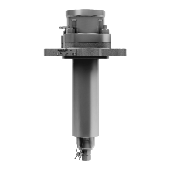
Internal-Style Pressure Relief Valve
A-1000 Series
Installation, Operation & Maintenance (IOM) Manual
P/N: A-1000, Rev. 3.2
Issue Date: April 10, 2018
Supersedes: A-1000, Rev. 3.1
Table of
Contents
Previous
Page
Next
Page
1
2
3
4
5
Advertisement
Table of Contents
Need help?
Do you have a question about the A-1075 and is the answer not in the manual?
Ask a question
Questions and answers
Related Manuals for Midland A-1075
Control Unit Midland A-1079 Installation, Operation & Maintenance Manual
A-1000 series internal-style pressure relief valve (42 pages)
Control Unit Midland A-1165 Installation, Operation & Maintenance Manual
A-1000 series internal-style pressure relief valve (42 pages)
Control Unit Midland A-1169 Installation, Operation & Maintenance Manual
A-1000 series internal-style pressure relief valve (42 pages)
Control Unit Midland A-22075 Series Installation, Operation And Maintenance Manual
Internal-style pressure relief valve (45 pages)
Control Unit Midland A-718C Series Installation, Operation & Maintenance Manual
1" angle valves (36 pages)
Control Unit Midland A-1477 Series Installation, Operation & Maintenance Manual
External-style pressure relief valve (37 pages)
Control Unit Midland A-520 Series Installation, Operation & Maintenance Manual
4" bottom outlet ball valve (28 pages)
Control Unit Midland A-522 Series Installation, Operation & Maintenance Manual
4" bottom outlet ball valve (28 pages)
Control Unit Midland A-207 Re-Assembly Instructions
Vacuum relief valves (4 pages)
Control Unit Midland A-7200 Installation, Operation & Maintenance Manual
Top-transfer ball valve (21 pages)
Control Unit Midland A-1076 Series Installation, Operation & Maintenance Manual
Internal-style pressure relief valve (40 pages)
Control Unit Midland A-14150 Series Installation Operation & Maintenance
External-style pressure relief valve (31 pages)
Control Unit Midland SD-250 User Manual
(20 pages)
This manual is also suitable for:
A-1100
A-1150
A-1247
A-1255
A-1280
A-1330
...
Show all
A-1300
A-1375
A-1450
A-1079
A-1165
A-1104
A-1154
A-1229
A-1169
A-1225
A-1251
A-1259
A-1304
A-1284
A-1334
A-1379
A-1100-f
A-1165-f
A-1075-f
A-1150-f
A-1225-f
A-1247-f
A-1280-f
A-1300-f
A-1255-f
A-1330-f
A-1104-f
A-1375-f
A-1079-f
A-1450-f
A-1154-f
A-1229-f
A-1251-f
A-1259-f
A-1169-f
A-1284-f
A-1304-f
A-1334-f
A-1379-f
Table of Contents
Save PDF
Print
Rename the bookmark
Delete bookmark?
Delete from my manuals?
Login
Sign In
OR
Sign in with Facebook
Sign in with Google
Upload manual
Upload from disk
Upload from URL


Need help?
Do you have a question about the A-1075 and is the answer not in the manual?
Questions and answers