Thermopatch Thermo-Seal Y151 User Manual
Hide thumbs
Also See for Thermo-Seal Y151:
- Manual (63 pages) ,
- Operator's manual (43 pages) ,
- User manual (63 pages)

Subscribe to Our Youtube Channel
Related Manuals for Thermopatch Thermo-Seal Y151


Summary of Contents for Thermopatch Thermo-Seal Y151
- Page 1 Y151 Thermo-Seal User manual ATTENTION! All persons involved in installation, commissioning, operation, maintenance and repair of this product should be made available to these instructions. V. 4.0 ENG V. 4.0 ENG Oct.2015 Jan2015...
-
Page 2: Copyrights
Copyrights © 2015, Thermopatch bv, Almere, The Netherlands. No part of this publication may be reproduced by any means without the prior written permission of Thermopatch bv, The Netherlands. Thermopatch and the Thermopatch logo, Thermoseal and Thermocrest are registered trademarks of Thermopatch. -
Page 3: Introduction
Introduction Dear User, Welcome to the growing group of Thermopatch users. Your purchase has been manufactured with the utmost care to ensure that you benefit as long as possible from your Thermopatch product. The products by Thermopatch are designed with special attention to your convenience. -
Page 4: Table Of Contents
Contents Copyrights Introduction Contents Declaration of Conformity 1. General description 1.1 Delivery 1.2 Conditions of warranty 2. Intended use 3. Technical specifications 3.1 Specifications of the Y-151 4. Overview of safety measures and warnings 4.1 Safety 5. Transport and storage 5.1 Transport 5.2 Storage 6. -
Page 5: Declaration Of Conformity
Thermopatch B.V. Draaibrugweg 14 1332 Almere The Netherlands herewith declare, on our own responsibility, that the machinery: Thermopatch Y-151 Thermoseal, which this declaration refers to, is in accordance with the conditions of the following Directive(s): 2006/42/EG (Machinery directive) 2004/108/EG (EMC directive) Based on DEKRA IEC 60950-1 test report nr. -
Page 6: General Description
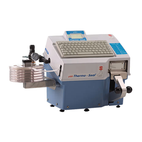
1. General description The Y151 Thermo-Seal is a machine for the temporary marking of garments and other textile items. Temporary marking of a garment or textile item is achieved without the use of chemical solvents or other harmful materials. By means of an ink ribbon cartridge, a code (maximum of 12 characters per label) is printed directly onto the Thermo-Seal label tape, and it is sealed directly onto the garment or textile item. -
Page 7: Delivery
If one of these articles should be missing or faulty, please contact your Thermopatch supplier. 1.2 Conditions of warranty Thermopatch points to its warranty and product liability conditions as laid down in our conditions of sales. These can be obtained at your Thermopatch supplier. -
Page 8: Intended Use
WARNING! Any use other than described above can be dangerous and cause damage and thus qualifies as ‘misuse’ which excludes Thermopatch bv from any liability. V. 4.0 ENG Oct. 2015 Manual Y151 V. 4.0 ENG EUR from original TPC 47117-MAN Rev 1214... -
Page 9: Technical Specifications
3. Technical specifications 3.1 Specifications of the Y-151 230 Volts Power consumption 575 Watts Power supply 230 Volt, 50/60 Hz Temperature 176 °C Machine height 389 mm Machine width 556.5 mm Machine depth (connections included) 432.5 mm Net weight 18.5 kg Platen Pad dimensions 14.3 x 34.7 mm Heater Unit dimensions... -
Page 10: Overview Of Safety Measures And Warnings
4. Overview of safety measures and warnings 4.1 Safety The Y151 Thermo-Seal machine has been designed with optimum safety for the machine operator in mind. However, there are some precautions that must be taken when operating and servicing the machine. Always turn off and unplug the machine when doing •... - Page 11 Warning symbols The following warning symbols have been mounted onto the machine for added safety: WARNING! Hot surface WARNING! Electric tension V. 4.0 ENG Oct. 2015 Manual Y151 V. 4.0 ENG EUR from original TPC 47117-MAN Rev 1214...
-
Page 12: Transport And Storage
Please let the machine cool down before packing the machine in the shipment container. 5.2 Storage When the machine needs to be stored, Thermopatch advises to use the original packaging. The machine should be stored on a pallet, off the floor, in dry conditions. -
Page 13: Operating Instruction
6. Operating instruction 6.1 Starting with the Y-151 Thermo-Seal The Y151 Thermo-Seal machine comes complete with an Ink Ribbon Cartridge, Thermopatch part INKCALC-2410. The Ink Ribbon Cartridge is required to print the desired code onto the temporary label tape. To Install the Ink Ribbon Cartridge: 1. -
Page 14: Inserting The Label Marking Tape
6.2 Inserting the label marking tape 1. Switch the Power Entry Module Switch “ON.” 2. Place the Label Marking Tape into a Label Tape Cas- sette and place the Cassette onto the Label Tape Cas- sette Storage Rack. 3. Pull out approximately 12” or 30cm of tape from the Label Tape Cassette. -
Page 15: Machine Operation
6.3 Machine operation Before printing and sealing with your Y151 Thermo-Seal machine, make sure you have completed all instructions for installation (see chapter 7. Assembly and Installation). In review, the following should be completed: • Loaded the Label Marking Tape into the Tape Feed Guide. •... -
Page 16: The Control Panel
6.4 The control panel Before you begin printing and sealing, you should understand the features, messages and icons present on the LCD panel of the Y151 Thermo-Seal machine. The picture of the LCD below illustrates the Y151 in “Ready” mode. A. -
Page 17: Customizing The Y-151 Thermoseal
6.5 Customizing the Y-151 Thermoseal The Y151 Thermo-Seal machine software has a number of factory default settings, such as: Sealing Temperature, the Display Language, the Label Marking Tape Length, and the Password to the Special Settings Mode. The Y151 Thermo-Seal software can be customized to your personal requirements. - Page 18 Menu Option #1 Settings Menu Menu Display Description Adjustment Default 1 = Tempera- Temperature Change tempera- / Key 1 °C/°F 176°C / ture ture 349 °F 2 = Seal Time 1 = Normal Time Change Normal / Key 0.1 second 2.7 sec Seal Time 2 = Extended Time Change Extended...
-
Page 19: Temporary Marking
Menu Option #2 Special Mode Menu Display Description Adjustment Default Type Password Password required Type in Password and press En- Password: to make changes to ter key Y150TP defaults Factory Reset Change factory set- Press Y for Yes, N for No Sure? Y - N tings Password on... -
Page 20: Sealing Label Tags And Organization
If there is no possibility for indirect marking, the garment or textile item must be washed in a washing net that has been marked. Be very careful when you want to mark articles that must be cleaned chemically. The message “Only Dry Cleaning”... - Page 21 Invoice Number System The number on the tag is the invoice number. It is often accompanied by the number of pieces, the day of delivery, the location or lot number. Tag color is usually changed after a set number of bundles or at the end of each day. 1.
- Page 22 Raise the press arm to seal the ends of the tape together. ATTENTION! Thermopatch cannot take any responsibility for any damages to garments or textile items that occur by the use of this machine. The Use of Flags on Sensitive Garments There is an alternative indirect Label Tag marking method.
-
Page 23: Assembly And Installation
7. Assembly and installation 7.1 Installation Take the Y151 Thermo-Seal out of the shipment container and put the machine on a worktable near a grounded socket. Ensure that there is sufficient free space around the machine. 7.2 Electrical requirements The Y151 Thermo-Seal should be connected to the electricity grid (230V or 115V alternating current). - Page 24 7.3 Pneumatic requirements The Y151 Thermo-Seal Machine also requires a clean dry air supply to operate properly. The line pressure coming into the Y151 Thermo-Seal Air Filter Pressure Regulator should be a minimum of 70 P.S.I. or 5 Bars. ATTENTION! This is not the final pressure setting for the Air Filter Pressure Regulator on the Y151 Thermo-Seal machine.
- Page 25 7.4 Label Tape Storage Rack Installation The Y151 Thermo-Seal machine comes complete with a Label Tape Storage Rack and six Label Tape Cassettes. The rack can hold a maximum capacity of eight Label Tape Cassettes. Attachment of the Label Tape Storage Rack to the machine chassis requires the use of a 4mm L-Hex Key.
-
Page 26: Maintenance Instructions
8. Maintenance instructions 8.1 Maintenance ATTENTION! Before beginning maintenance, unplug the Main Air Supply Line Hose to the Air Filter Pressure Regulator and unplug the Line Power Cord from the electrical supply. Before beginning any maintenance on your Y151 Thermo- Seal machine, finish any process cycles that may be started. - Page 27 Heater Shield Clean the Heater Shield several times a day. To clean the Heater Shield, use the provided cleaning paste, “Ez-Off” (Thermopatch #DH-6873 or SPADH-6873). Ez-Off cleaning paste is available for purchase through our Customer Service network. To clean the Heater Shield, put some paste on a dry cloth and clean the Heater Shield while it is still warm, but not hot enough to cause burns to your skin.
- Page 28 Label Tape Drive “O”-Ring The Label Tape Drive “O”-Ring transports the Label Marking Tape through the Tape Guide. The Label Tape Drive “O”-Ring is a part that will wear over a period of time. The life cycle of this part is relative to the amount of machine usage. The following narrative with sequence of pictures will take you through the process of removal and installation of a new Label Tape Drive “O”-Ring.
-
Page 29: Technical Annexes
9. Technical annexes Guide. 9.1 Drawings and Parts Listing On the following pages, the reader will find technical drawings and corresponding parts listings of the Y151 Thermo-Seal machine. The technical drawing illustrating a particular sub-assembly or area of the machine will precede the parts listings. -
Page 30: Wiring Diagram
9.1.2 Electrical Drawings 9.1.2.1 Wiring Diagram KEYBOARD LCD PANEL PRINT HD. #20200-48 #20081-100 #20205-142 POWER ENTRY MODULE #20056-77 FUSES 115v [2] x 6.3a #20015-32 230v [2] x 3.15a #20015-26 SOLID STATE RELAY PS/2 #20040-68 LCD PANEL HEATER SERIAL SAFETY TEMP T°... -
Page 31: Electrical Chassis Assembly
9.1.2.2 Electrical Chassis Assembly Electrical Chassis Assembly (P/N #####) Partnumber 47091 V. 4.0 ENG Oct. 2015 Manual Y151 V. 4.0 ENG EUR from original TPC 47117-MAN Rev 1214... -
Page 32: Heater Unit Assembly
9.1.2.3 Heater Unit Assembly Item# Description Quantity Partnumber heater unit assembly 47111 heating element assembly 47123 RTD Temperature Sensor Assembly 47136 V. 4.0 ENG Oct. 2015 Manual Y151 V. 4.0 ENG EUR from original TPC 47117-MAN Rev 1214... -
Page 33: Press Arm Switch Assembly
9.1.2.4 Press Arm Switch Assembly Partnumber 47071 Note: This Press Arm Switch (47071) is installed in machines prior to July 2015, through Serial Number: Y1512AE342. Press Arm Switch Assembly (P/N 47071) V. 4.0 ENG Oct. 2015 Manual Y151 V. 4.0 ENG EUR from original TPC 47117-MAN Rev 1214... - Page 34 Press Arm Switch Assembly-2 Note: This Press Arm Switch-2 is installed in machines beginning in July 2015 and thereafter (Serial Number: Y1512AE343 and thereafter). Item# Description Quantity Partnumber 1 M4 X 0.7 X 25 MM HEX SCHS 2 21043-13-C 2 HEX NUT, M4 X 0.7 2 21045-06-E 3 OMRON SWITCH: DZ-10GW-1B 1 20055-101...
-
Page 35: Pneumatic Diagram
9.1.3 Pneumatic Drawings 9.1.3.1 Pneumatic Diagram Air Filter Pressure Regulator Assembly Exhaust Breather Solenoid Valve Press Arm Cylinder 5/32" Dynamic Knife Cylinder Pneumatic Diagram V. 4.0 ENG Oct. 2015 Manual Y151 V. 4.0 ENG EUR from original TPC 47117-MAN Rev 1214... -
Page 36: Press Arm Cylinder Assembly
9.1.3.2 Press Arm Cylinder Assembly Item# Description Quantity Partnumber Socket Hex Set Screw, M10 X 1.5 X 30mm 21049-13-H Press Arm Cylinder 22010-74 Exhaust Breather 22046-24 Socket Hex Cap Screw, M6 X 1.0 X 90mm 21043-25-E Pneumatic Solenoid Valve 22046-23 Cylinder Rod End Assembly Solenoid Valve Wire Harness 47084... -
Page 37: Air Filter Pressure Regulator Assembly
9.1.3.3 Air Filter Pressure Regulator Assembly Partnumber Air Filter Pressure Regulator Assy. 47094 Item# Description Quantity Partnumber Air Pressure Gauge 22045-101 Quick Connect Hole Adapter DH-6797 Air Filter Pressure Regulator 22045-91 Air Filter Pressure Regulator Assembly Part Number 47094 V. 4.0 ENG Oct. -
Page 38: Dynamic Knife Actuating Spring Assembly
9.1.4 Mechanical Drawings 9.1.4.1 Dynamic Knife Actuating Spring Assembly Static Knife Blade Dynamic Knife Blade Item# Description Quantity Partnumber Static Knife Blade 47109 Cutter Actuator 47228 Dynamic Knife Assembly Nylon Locknut 21051-31-G M5 Flat Washer 21047-06 M5 Hex Nut 21045-07-A Set Screw 92311A431 Knife Actuation Spring Assy... -
Page 39: Dynamic Knife Assembly
9.1.4.2 Dynamic Knife Assembly Y-150 only Static Knife Blade Dynamic Knife Blade Item# Description Quantity Partnumber Static Knife Blade 47109 Nylon Washer, D 1/4” Inside 21028-63 Dynamic Knife Assembly Socket Hex Shoulder Screw, 1/4” x 3/8” 21006-01-G long (#10-31 unc) Dynamic Knife Push Pod 47203 Hex Jam Nut, M5 x 0.8... -
Page 40: Machine Top Cover Assembly And Accesories
9.1.4.3 Machine Top Cover Assembly and Accesories Item# Description Quantity Partnumber Machine Cover Assembly and Accesssories Leftside Lower Machine cover 47066 M6 Nylon Washer 21028-63 Hex Socket Button Head Screw, M6 x 1.0 x 21006-01-G 12 mm Label Tape Cassette Rack 47068 Hex Socket Button Head Screw, M6 x 1.0 x 21061-26-N... -
Page 41: Printer Head Assembly
9.1.4.4 Printer Head Assembly Item# Description Quantity Partnumber Printer Head Mask 20205-143 Printer Head 20205-142 Printer Head Assembly Socket Hex Cap Screw, M3 x 0.5 x 12 mm 21043-07-B M3 Spring Lockwasher 21046-03-A V. 4.0 ENG Oct. 2015 Manual Y151 V. 4.0 ENG EUR from original TPC 47117-MAN Rev 1214... -
Page 42: External Tape Guide Assembly
9.1.4.5 External Tape Guide Assembly Arm Compression Spring Part Number 24075-33 Te on Tape Guide Shield Part Number 47108 Adhesive side of Te on Guide Shield faces toward External Tape Guide Pressure Idler Wheel Part Number 47042 Socket Hex Shoulder Screw M6 x 12mm Tape Guide Thumb Screw Part Number 47087... -
Page 43: Machine Top Cover & Lcd Panel Assembly
9.1.4.6 Machine Top Cover & LCD Panel Assembly NOTE: TO IMPROVE CLARITY, KEYBOARD USB CABLE HAS NOT BEEN SHOWN NOTE: VELCRO HOOK & LOOP SECURED TO TOP OF COVER NOTE: AFTER MOUNTING TO PASS KEYBOARD USB UNDERSIDE OF KEYBOARD CABLE THROUGH SLOT IN TOP OF COVER Item# Description... -
Page 44: Dynamic Knife Actuating Spring Assembly
9.1.4.7 Dynamic Knife Actuating Spring Assembly For machines manufactured from beginning 2015. Please refer to fig. 9.1.4.1 for full view of dynamic and static blades. SPA 47292 Dynamic Knife Actuation Spring Assembly Item# Description Quantity Partnumber SPA47292 Dynamic Knife Actuation Spring Assembly Actuator Bracket SPA47193 Static Knife Blade... -
Page 45: Additional Installation Instructions
9.2 Additional Installation Instructions • Ez-Off cleaning paste SPADH-6873 TP Part number 47318-INSTR Y151T-110/220 Mechanical Knife Kit (47318-KIT) Installation Instructions Kit contents: Quantity TP Part Number Description 21067-02-B SHOULDER SCREW HEX SOCKET M6X12 (M5x0.8 THD) 47315 Back Actuator Plate 21028-70 HEX 2X Female Standoff/Spacer (M5 x 50 MM x 9) 21045-07-A HEX NUT M5 x 0.8... - Page 46 24085-14 4.0 MM ALLEN HEX KEY WRENCH Instructions to remove the Dynamic Knife Actuation Spring Assembly (SPA47292) 1. Turn off and remove all power to the Y151T-110/220 Machine 2. Lift up the Top Cover of the Y151T-110/220 Machine 3. Remove the Label Tape Cassette and Label Tape Cassette Rack •...
- Page 47 • Remove the Button Head Hex Socket Screw and place the Air Regulator/Filter/Gauge down 5. Remove the Left Side Lower Machine Cover from the Y151T-110/220 Machine • Locate the Left Side Lower Machine Cover • Insert a 4 mm Allen Hex Key Wrench into the (4) Button Head Hex Socket Screw (21061-20-N) located on the Left Side Lower Machine Cover •...
- Page 48 tubing • Insert a 5/32” Plug (22020-07) into the elbow 7. Remove the black tubing from the Dynamic Knife Actuator Cylinder • Locate the black tubing at the bottom of the Dynamic Knife Actuation Cylinder (47204) • Remove the black tubing from the bottom of the Dynamic Knife Actuation Cylinder by pushing up against the black knob and pulling down on the black tubing 8.
- Page 49 Spring Assembly from the Y151T-110/220 Machine • Keep all hardware and parts 9. Remove the Dynamic Knife Pivot Block • Locate the M5 Hex Nut Elastic Lock (21051-31-G) on the Dynamic Knife Assembly • Insert a 8mm Wrench around the M5 Hex Nut Elastic Lock •...
- Page 50 • Remove the Cutter Actuator and the Blade Dynamic Knife from the Dynamic Knife Block Assembly 10. Assemble the Dynamic Knife Block Assembly Locate the following parts: • (2) Button Head Hex Socket Screw (21061-17-R) • (2) Lock Washer, Split Lock (21046-03-A) •...
- Page 51 • Insert (2) Socket Hex Cup Point Set Screw on top of the Stanchion, Right • Insert a 1.5 mm Allen Hex Key Wrench into the Socket Hex Cup Point Set Screw and screwed on just to touch the Knife Pivot Shaft •...
- Page 52 and keep it in place • Insert a 6 mm Wrench around the Hex Lock Nut and screw tightly 13. Part 2: Assemble the Mechanical Knife Assembly • Locate the following parts • Shoulder Screw, Hex Socket (21067-02-B) • Flat Washer (21047-07) •...
- Page 53 Note: Adjust accordingly; the Press Arm movement should not be stopped by the Dynamic Knife construction 14. Assemble the Left Side Lower Machine Cover to the Y151T-110/220 Machine • Locate the following parts • Left Side Lower Machine Cover • (4) Button Head Hex Socket Screw (21061-20-N) •...
- Page 54 Dynamic Knife is cutting the label with a clean cut edge 21. Pull down the Top Cover of the Y151T-110/220 Machine Instructions to remove the Dynamic Knife Actuation Spring Assembly (47292) Follow the Dynamic Knife Actuation Spring Assembly Removal Instructions •...
- Page 55 Removal Instructions • Follow Steps 9-21 from “Dynamic Knife Actuation Spring Assembly (SPA47292) Removal Instructions” Y151T-110/220 Press Arm Switch Assembly (47314) Installation Instructions 47314-INSTR Parts provided: Quantity TP Part Number Description 21043-13-C M4 X 0.7 X 25 MM HEX SCHS 21045-06-E HEX NUT, M4 X 0.7 20055-101...
- Page 56 • The wiring harness is not included with the Press Arm switch assembly as shown below FIGURE 1. Press Arm Switch Assembly (47314) TOOLS REQUIRED • PHILLIPS HEAD (CROSS HEAD) SREW DRIVER (NOT INCLUDED WITH THE MACHINE) • 4 MM DIN 911 HEX DRIVE SHORT ARM STANDARD L SHORT ARM HEX KEY (P/0 47311 METRIC TOOL KIT) •...
- Page 57 through Serial Number: Y1512AE342. • TURN OFF THE POWER FROM THE MACHINE. REMOVE THE PLUG FROM THE WALL SOCKET. • REMOVE 5 MM HEX SCREWS FROM THE BASE OF THE SWITCH FRAME USING THE 5 MM HEX KEY WRENCH • CAREFULLY REMOVE THE PRESS ARM SWITCH ASSEMBLY Wiring Harness Terminal Screws...
- Page 58 THE PRESS ARM SWITCH USING A PHILLIPS HEAD (CROSS HEAD) SCREW DRIVER. DO NOT DISCARD THE HARDWARE FIGURE-2. Press Arm Switch Assembly (47071) ASSEMBLING THE PRESS ARM SWITCH (47314) AS SHOWN IN FIGURE-3. • CAREFULLY RECONNECT THE PRESS ARM SWITCH WIRING HARNESS FOUR WIRES TO THE SWITCH SCREW TERMINALS WITH THE PHILLIPS HEAD (CROSS HEAD) Front side of...
- Page 59 ARM SWITCH INSTALLATION OF THE NEW PRESS ARM SWITCH (47314) • CAREFULLY INSTALL THE NEW PRESS ARM SWITCH INTO THE BOTTOM OF THE CHASSIS AS SHOWN IN FIGURE-4. FIGURE-4. INSTALLATION OF THE PRESS ARM SWITCH ASSEMBLY • MOVE THE PRESS ARM SWITCH BRACKET SO THAT THE MOUNTING HARDWARE IS TOUCHING THE REAR SIDE OF THE MOUNTING HOLES AS SHOWN IN FIGURE-5.
-
Page 60: Faults
10. Faults If a problem should occur, please consult the list below; if the problem you are facing cannot be solved by yourselves then contact your supplier. Fault Possible cause Solution • • Machine does not function Not connected to outlet Check outlet •... - Page 61 Fault Possible cause Solution • • Label Marking Tape is Tape Guide is dirty Clean the tapeguide jamming in the Tape Guide inside and outside, see pg 26 Tapeguide • • Splice ijn label Marking Tape, or Remove the marking folded tape in the tape guide tape and cut out the splice or the folded part.
-
Page 62: End Of Life
11. End of life Choose to dispose of the machine responsibly when it has reached its end of life. Electrical machinery, accessories and packaging should be recycled as much as possible in an environmentally responsible manner. - Dismantle the machine groups: steel parts / pneumatic components / electrical components - These can be separated and returned for recycling. - Page 63 T +31 36 549 11 11 T +31 36 549 11 11 F +31 36 532 03 98 F +31 36 532 03 98 sales@thermopatch.nl sales@thermopatch.nl Thermopatch Australia Pty Ltd Thermopatch Australia Pty Ltd Australia Australia T +61 395325722 T +61 395325722...
Need help?
Do you have a question about the Thermo-Seal Y151 and is the answer not in the manual?
Questions and answers