Table of Contents
Advertisement
Quick Links
Advertisement
Table of Contents

Subscribe to Our Youtube Channel
Related Manuals for Thermopatch Deco-Print DP2000T


Summary of Contents for Thermopatch Deco-Print DP2000T
- Page 1 Thermopatch DP2000T Deco-Print Operator's Manual Rev 1215...
-
Page 2: Table Of Contents
Contents WARRANTY..............................6 Section 1 ..............................7 Introduction to the Deco-Print, from Thermopatch ................7 Section 2 ..............................11 DP2000T SETUP ............................. 11 Step 1 ..............................11 Step 2 ..............................13 Step 3 ..............................13 Step 4 ..............................14 Step 5 ..............................15 DP2000T Transfer Specifications ...................... - Page 3 Compressed Air Supply ......................... 51 General ..............................51 Teflon/Fiberglass Shield (Used for Heat Sealing) .................. 51 Shipping the DP2000T ........................... 51 Section 7: Customer Service ........................52 Thermopatch Customer Service ......................52...
- Page 4 Figures Figure 1 — Control Box Bracket ........................ 11 Figure 2 — Display ............................ 12 Figure 3 — Electrical Plugs Connected ..................... 12 Figure 4 — Heater Cover Assembly, Installation ..................13 Figure 5 — Air Filter/Regulator, Installation ..................... 13 Figure 6 —...
- Page 5 Figure 30 — AC Harness ..........................48 Figure 31 — DC Harness ........................... 49 Figure 32 — Head Cover Assembly ......................50...
-
Page 6: Warranty
WARRANTY Thermopatch Corporation, Syracuse, New York (“Seller”) warrants this product to be free from defects in material and workmanship under normal use and service. Any part which proves to be defective in material or workmanship within one year of the date of original purchase for use, will be repaired or replaced, at Seller’s option, free of service or labor charges, with a new or functionally operative part. -
Page 7: Section 1
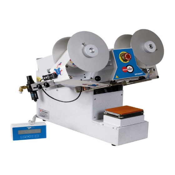
PLEASE NOTE: The time, temperature, and pressure settings needed to seal these products with the DP2000T may differ from the settings needed by other Thermopatch heat seal equipment. Contact a Thermopatch representative with any questions. The DECO-PRINT model DP2000T prints a permanent mark directly onto most natural or synthetic fabrics by means of a printing plate, briefly striking the inked ribbon against the material to be marked. - Page 8 ACCESSORIES INCLUDED: • 45658 — Sealing kit. Use for sealing labels, mending materials and applying hot paper transfers • 46780 — (3) Separator discs. Used between different colored ribbon rolls (C-TAPE) on supply side. See page 21. • 46007 — Plate holder. •...
- Page 9 Safety Information Each DECO-PRINT machine is equipped with a Safety Guard feature for the protection of the operator. The Safety Guard is activated in two ways: 1. The metal bar senses the touch of your hand. 2. There are switches that sense any obstruction. Once the safety guard is activated, the downward movement of the print will be interrupted and the “CLEAR”...
- Page 10 MACHINE SPECIFICATIONS Electrical Requirements: 5 Amps @ 110 VAC 50/60 HZ 2.5 Amps @ 220 VAC, 50/60 HZ Operating Air Pressure: 25 PSI (1.8 BAR) Minimum to 70 PSI (4.8 BAR) Maximum 1.3 CFM (0.6 Liters/sec) Dwell Time Setting: 0.1 Seconds to 99.9 Seconds Heat Range: 200°-500°F (93°...
-
Page 11: Section 2
Section 2 DP2000T SETUP Step 1 Refer to Figure 1 Loosen the two screws on the top of the case in the back and install the control box bracket, Item 4. Figure 1 — Control Box Bracket... -
Page 12: Figure 2 - Display
Plug one side of the display cable, Item A, into the control box, Item B, connector. Figure 2 — Display Plug the other end of the display cable, Item C, into the connector on the side of the machine. Figure 3 — Electrical Plugs Connected... -
Page 13: Step 2
Step 2 Refer to Figure 4. Turn the “Emergency Stop” switch, Item A, in the direction of the arrow to make sure it is out. Figure 4 — Heater Cover Assembly, Installation Step 3 Refer to Figure 5 Attach the air filter/regulator, with fittings to the bulkhead fitting, Item A, on the back of the machine. Orient as shown with the gauge facing forward. -
Page 14: Step 4
Step 4 Refer to Figure 6. This is the Electrical Enclosure Assembly, found on the right side of your machine Connect the foot pedal plug into the FOOTSWITCH Plug, Item A. Connect the power line cord to power entry module, Item B, and to the power outlet. Turn on the machine by pressing the on/off switch, Item D. -
Page 15: Step 5
Step 5 Refer to Figures 7 & 8 Place flange assemblies, Item A, on supply and take-up shafts, Item B. Figure 7 — Head Assembly, no Flanges Figure 8 — Head Assembly, with Flanges... -
Page 16: Figure 9 - Transfer Roll Threading
Figure 9 — Transfer Roll Threading... -
Page 17: Figure 10 - Ribbon Roll Threading
Figure 10 — Ribbon Roll Threading... -
Page 18: Dp2000T Transfer Specifications
DP2000T Transfer Specifications DP2000T Transfer Setup 1. Select the transfer for use and measure the distance from the leading edge of one image to the leading edge of the next transfer as shown. A special platen is required if this measurement is less than 2-1/2 inches ( 64 mm ) 2. -
Page 19: Figure 11 - Sensor
7. Press the ENTER button until the display reads “PATTERN MARKER: “. Use the UP or DOWN ARROW button to select YES. 8. Press the MENU button to exit the menu. 9. Loosen the clamp screw, move the transfer sensor onto the space between the transfer images and tighten the clamp screw. -
Page 20: Figure 13 - Sensor Position
11. Loosen the clamp screw and move the transfer sensor towards the leading edge of the transfer image closest to the sealing iron. When the edge of the image is detected by the transfer sensor, an asterisk ( * ) will appear on the display next to the feed length. When you see the asterisk ( * ), on the display, tighten the clamp screw. -
Page 21: Ribbon Tape Setup Feed Adjustment
Ribbon Tape Setup Feed Adjustment The first step is to adjust the feed. This feed value advances the tape after printing to the amount of the entered value, to set up for the next print. Using the control box, the user adjusts and controls the distance that the machine feeds. -
Page 22: Adjusting The Printing Pressure And Platen Height Printing Pressure
Adjusting the Printing Pressure and Platen Height printing Pressure Printing pressure is preset at the factory to 50 PSI. The printing pressure range is from 25 PSI (1.8 BAR) minimum to 70 PSI (4.8 BAR) maximum. NEVER EXCEED 70 PSI. In general, the larger the printing area, the higher the pressure required. -
Page 23: Inserting The Printing Plate
INSERTING THE PRINTING PLATE The above drawing shows a DP2000T Printing Plate (Item 1) (CUSTOM PART) and a Printing Plate Holder (Item2) P/N (46007). The Printing Plate Holder is provided for installation and removal of the Printing Plate. • With the artwork facing down on the Printing Plate, apply a downward force just enough to slide the Printing Plate Holder forward. -
Page 24: Choosing The Platen
Choosing The Platen Be sure to use the proper platen. Use the hard rubber platens for printing, and the soft rubber platen for heat sealing and dry ink transfers. There should be a distance of at least 1/8” to 1/4” between the printed image and the outer edge of the platen. -
Page 25: Section 3
Section 3 CONTROL BOX The Deco-Print machine features a digital control box, with six control buttons, shown below: The display on the control box in normal running mode shows: Feed Length * Print Time * (means sensor is sensing stop position on transfer) Temperature Daily Counter... - Page 26 The MACHINE SETUP menu is used to set: 1. Display language (English, Nederlands, Italanio, Deutsch, Francais, Espanol) 2. Temperature scale (Fahenheit, Celcius) 3. Feed length (Inches, Millimeters) 4. Counter mode (Daily, Continuous) The JOB SETUP menu is used to set: 1.
-
Page 27: Machine Setup
Machine Setup Press MODE to show choice of JOB SETUP or MACHINE SETUP. Press UP or DOWN button to select MACHINE SETUP. 1. Press ENTER and select language. Press UP or DOWN button to select ENGLISH. 2. Press ENTER and choose the temperature scale. Press UP or DOWN button to select FAHRENHEIT. -
Page 28: Section 4: Troubleshooting
Section 4: Troubleshooting Before referring to the information below, check for proper set-up and operation as outlined in “DP2000T Setup”. Solutions are listed with the most probable ones listed first. Some procedures may require completion by a person with some mechanical and electrical skill. Call Customer Service for assistance or to order replacement parts. - Page 29 Print head will Touch guard activated Press Clear not descend Temperature not ready Wait Solenoid air valve not shifting Replace Air supply not connected Check Foot switch is unplugged or bad Check/Replace Leak or restriction in air line or connections Check/Repair Print head too Flow control(s) adjustment is incorrect...
- Page 30 When type slugs Type slugs are dirty Clean are used, print is Deformed type slugs caused by high heat Adjust heat per pg unclear 27; replace slugs Check & Correct Pressure incorrect Ink marks on back Ink build-up on rubber platen Clean Platen.
-
Page 31: Operational Messages
Relay is bad or shorted; temperature sensor is bad or shorted; or bad connections High temperature Heater failure Contact Thermopatch Unknown Seal Switch ERR This indicates the seal down switch was not activated During a seal cycle if the top platen did not come... -
Page 32: Section 5: Parts Identification And Location
Section 5: Parts Identification and Location Figure 14 — DP2000T Machine Assembly ITEM NO. PART NUMBER DESCRIPTION QTY. 46876 CASE WELDMENT PLATEN ASSEMBLY SEE PAGE 33 46882 COVER, TOP REAR 46788 BRACKET, CONTROL BOX 21021-06-C NO. 8 SPLIT LOCKWASHER 21028-36 HEX STANDOFF #8-32 45678 COVER, CASE FRONT... -
Page 33: Figure 15 - Platen Assembly
Figure 15 — Platen Assembly ITEM NO. PART NUMBER DESCRIPTION QTY. 45587 PLATEN BLOCK 45619 RETAINER, PLATEN HOLDER 45582 PLATEN HOLDER GUIDE WELDMENT 45621 PLATEN HOLDER 45642 SCREW ASSY 21029-32 THUMB SCREW 1/4-20 X 3/4 LG X 3/4 21062-03-D FLAT SOC HD SCR 8-32 X 1/2 24075-26 SPRING - COMPRESSION 46833... -
Page 34: Figure 16 - Press Arm Assembly
Figure 16 — Press Arm Assembly ITEM NO. PART NUMBER DESCRIPTION QTY. 45591 ARM SUPPORT ASSY 22010-57 PIVOT MOUNT BRKTS (BIMBA) AIR CYLINDER, 2 1/2 BORE 3 1/2 22010-56 45578 UPPER LINK ASSY 46055 LOWER LINK ASSY 45589 CLEVIS, SEALING CYLINDER 21051-20-C NUT, HEX JAM 1/2-20 45593... -
Page 35: Figure 17 - Heater Assembly
Figure 17 — Heater Assembly ITEM NO. PART NUMBER DESCRIPTION QTY. 45585 SEALING IRON MACHINING 110V 45579 ISOLATOR BLOCK 45849 GUIDE WELDMENT, 45643 STOP, PRINTING PLATE 21021-10-C LOCKWASHER #5/16 SPLIT 21050-192 SHCS 5/16-18 X 2.0 LG S.S. 21021-06-C NO. 8 SPLIT LOCKWASHER 21069-05-E PHS 6-32 X 3/8 LG SS 21069-03-E... -
Page 36: Figure 18 - Support & Switch Assembly
Figure 18 — Support & Switch Assembly ITEM NO. PART NUMBER DESCRIPTION QTY. 45576 STUD, PIVOT 21062-05-G FHSCS 1/4 - 20 X 3/4 LG 21021-09-C LOCKWASHER - SPLIT 1/4 21061-03-F BUT HD SCR 1/4 X 20 X 1/2 45613 BRACKET, SEAL SWITCH 45712 NUT PLATE, SEAL SWITCH 20055-73... -
Page 37: Figure 19 - Head Assembly
Figure 19 — Head Assembly ITEM NO. PART NUMBER DESCRIPTION 46893 FLANGE ASSY 46916 DRIVE ROLL ASSY TOUCH GUARD ASSY SEE PAGE 42 COVER ASSY, HEATER SEE PAGE 43 REAR PLATE ASSY SEE PAGE 39 21011-04-K SET SCREW 10-32 X 3/16 LG COVER ASSY, HEAD SEE PAGE 5-13 21063-05-K... -
Page 38: Figure 20 - Front Plate Assembly
Figure 20 — Front Plate Assembly ITEM NO. PART NUMBER DESCRIPTION 46899 BRACKET, SENSOR 46900 SHAFT, SENSOR ROLL 46901 PLATE, SENSOR BRACKET SPACER 46902 SPACER, CLAMP SCREW 21023-02 WASHER, FLAT 1/4 21006-01-B SHOULDER SCREW 5/16 X 3/8 LG 21050-232 BELLEVILLE DISC SPRING .317 X .625 X .042 D-9702 E-RING 1/4 20055-73... -
Page 39: Figure 21 - Rear Plate Assembly
Figure 21 — Rear Plate Assembly ITEM NO. PART NUMBER DESCRIPTION QTY. 46886 PLATE, REAR 46778 SHAFT, UNWIND D-9705 E-RING 3 / 8 46936 BRACKET, LASER SPRING 46915 SHAFT, DRIVE ROLL 46919 PIN, DRIVE ROLL SPRING DF-7180 SPRING - EXT LE-029C-4 D-9701 E-RING 3 / 1 6 D-9702... -
Page 40: Figure 22 - Laser Assembly
Figure 22 — Laser Assembly ITEM NO. PART NUMBER DESCRIPTION QTY. 46922 YOKE, LASER 46934 PIVOT BLOCK, LASER 46933 PIN, LASER BLOCK 46935 BRACKET, LASER BLOCK D-9701 E-RING 3/16 21058-03-F PHS 8 - 32 X 1/4 LG 21021-06-C NO. 8 SPLIT LOCKWASHER 21011-04-H SET SCREW 8-32 X 3/16 LG 46896... -
Page 41: Figure 23 - Dancer Roller Assembly
Figure 23 — Dancer Roller Assembly ITEM NO. PART NUMBER DESCRIPTION QTY. 46912 BLOCK, LEAF SPRING 46914 LEAF SPRING 46913 HANDLE, SPRING 46909 SHAFT, PIVOT 46905 DANCER ROLL ARM 46910 ARM ASSY, SPRING 21011-04-K SET SCREW 10-32 X 3/16 LG D-9702 E-RING 1/4 21021-07-C... -
Page 42: Figure 24 - Touch Guard Assembly
Figure 24 — Touch Guard Assembly ITEM PART NUMBER DESCRIPTION QTY. 46053 SPRING BRKT, R.H. 46054 SPRING BRKT, L.H. 21022-12 THRUST WASHER 3/8 46056 PIN, SHOULDER 21050-111 COTTER PIN 1/16 X 1/2 LG 45612 SPRING RETAINER 24075-39 SPRING, COMPRESSION 21060-04-C BHS 4-40 X 5/16 LG 21021-03-C NO. -
Page 43: Figure 25 - Heater Cover Assembly
Figure 25 — Heater Cover Assembly ITEM PART DESCRIPTION QTY. NUMBER 46884 COVER, HEATER 45597 TAPE GUIDE 46938 LABEL, DP2000T FRONT 20055-75 STOP SWITCH ACTUATOR 20056-28 CONTACT BLOCK, E-STOP 21021-06-C NO. 8 SPLIT LOCKWASHER 21069-03-F PHS 8-32 X 1/4 LG SS 46880 SCALE, 4"... -
Page 44: Figure 26 - Pneumatic Diagram
Figure 26 — Pneumatic Diagram ITEM NO. PART NUMBER DESCRIPTION QTY. DH-6786 NIPPLE - HEX 1/4 NPT DH-6761 ELBOW - 90 DEG 1/4 NPT DH-6797 ADAPTER - MALE HOSE 1/4 MNPT 22030-38 FITTING - BULKHEAD 1/4 NPT 22046-09 AIR FLOW CONTROL RT ANGLE 1/4 NPT 22015-34 ELBOW - 1/4 MPT X 3/8 TUBE 22005-45... -
Page 45: Figure 27 - Valve And Regulator Assembly
Figure 27 — Valve and Regulator Assembly ITEM PART DESCRIPTION QTY. NUMBER 22045-91 AIR REGULATOR/FILTER/GAUGE 0-150 PSI DH-6786 NIPPLE - HEX 1/4 NPT DH-6761 ELBOW - 90 DEG 1/4 NPT DH-6797 ADAPTER - MALE HOSE 1/4 MNPT 22030-38 FITTING - BULKHEAD 1/4 22045-89 VALVE - IN LINE CHECK 1/4 NPT 22046-09... -
Page 46: Figure 28 - Electronics Module
Figure 28 — Electronics Module... -
Page 47: Figure 29 - Main Electronics Module
Figure 29 — Main Electronics Module... - Page 48 Figure 30 — AC Harness...
- Page 49 Figure 31 — DC Harness...
- Page 50 Figure 32 — Head Cover Assembly ITEM PART DESCRIPTION QTY. NUMBER 46883 COVER, HEAD 21029-60 THUMB SCREW, 1" DIA KN'D HD, 1/4x20x1-1/4 LG D-7212 ACORN HEX NUT 1/4-20 45426 LABEL, HIGH VOLTAGE 46945 LABEL, LASER TARGET...
-
Page 51: Section 6: Maintenance
Section 6: Maintenance Rubber Print Platen Clean often by wiping with a soft, clean rag. Replace the pad when it becomes worn. To replace pad, slide old pad assembly out of the lower platen, and install a new assembly. Compressed Air Supply Maintain a filtered air supply. - Page 52 Customer Service Department, offer their assistance in the development of effective heat-seal mending, marking, and identification programs. Thermopatch markets a complete line of heat-seal and marking machines, as well as a complete line of materials and supplies. • Label Print Machines – Manual, automatic, and computer controlled.
- Page 53 B.P. 1011 26127 Oldenburg Les Mureaux Cedex 78131 Deutschland France Telephone: 011-33-1-3022-0808 Telephone: +49 441-380210 Fax: 011-33-1-3022-1866 Fax: +49 441-3802121 Internet Address: http://www.thermopatch.com E-mail Address: sales@thermopatch.com If your country is not listed above, please contact Thermopatch Corporation or Thermopatch Netherlands.
Need help?
Do you have a question about the Deco-Print DP2000T and is the answer not in the manual?
Questions and answers