Table of Contents
Advertisement
Quick Links
Advertisement
Table of Contents

Related Manuals for FlowLine EchoWave LG10 Series


Summary of Contents for FlowLine EchoWave LG10 Series
- Page 1 EchoWave Guided Wave Liquid Level Transmitter LG10 & LG11 Series Quick Start ©2019 Flowline, Inc. All Rights Reserved Made in USA Flowline, Inc. | 10500 Humbolt Street, Los Alamitos, CA 90720 p 562.598.3015 f 562.431.8507 w flowline.com QS300840 Rev A2...
-
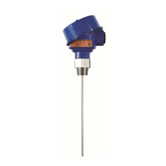
Page 2: Sensor Models
If you have a non-standard installation or setup requirement that is ® not addressed here, please refer to the EchoWave Manual or other support documentation located at flowline.com. WE DO YOUR LEVEL BEST ® Thank you for purchasing EchoWave . - Page 3 ® STEP 2: INSTALL WEBCAL SOFTWARE ® Download WebCal software from www.flowline.com/webcal-software onto a PC with the following minimum specifications: ® ® Windows XP/Vista/7/8/10, 32 or 64-bit system, 10 MB storage space, 256 MB RAM, 1 USB 2.0 port...
-
Page 4: Step 4 - Sensor Configuration
STEP 4 - SENSOR CONFIGURATION Configures the relays in terms of pump/valve operations and level alarms as well as the setting fail-safe for relays and signal output. Loop Fail-Safe - Allows selection of fail-safe current output if the sensor looses echo confidence (LOST). Note: Choose Hold Last Value setting when your application level either falls below the end of the... - Page 5 STEP P 6 - TANK L LEVEL CONF FIRMATION Verif fy the Heigh t Units, Sens sor Height, P Probe Lengt th, Max. Fill- -Height & Mi n. Fill-Heigh ht Settings. All values were e calculated and set in th he previous Dimensiona al Entry wind...
-
Page 6: Step 7 - Write To Unit
® * For complete information on the WebCal software, please refer to the WebCal manual located at flowline.com/webcal-software. Before configuration can be completed: You must click the Write to Unit button to save the settings to the unit. ... -
Page 7: Mounting Considerations
® STEP 8 - MOUNTING ECHOWAVE ® EchoWave is mounted vertically into the tank via its connection thread. It is then screwed directly into a standard threaded tank connection, i.e. tank adapter, bushing, weld-in socket, or it can be screwed into a flange which is connected to a tank nozzle. - Page 8 ® STEP 9 - WIRING ECHOWAVE ® Analog Output (4-20 mA): The analog output of the EchoWave is a sourced 4-20 mA control circuit. The typical way to use this feature is to connect a positive supply to the (+) input terminal, a negative supply to the (-) input terminal and to connect the current output out of the 420 (+) terminal.
-
Page 9: Wire Connections
WIRE CONNECTIONS The housing has single cable entry and can be attached to screw plugs, cord grips or conduit with the ½” NPT thread. Note: the customer must confirm the suitability of those connectors for the specific application requirements and cabling; and replace them when necessary. IP66-rated screw plugs and cord grips have to be properly mounted and tightened around cable of suitable type and diameter to ensure the IP66 rating of the housing. - Page 10 COMMON WIRING TO DISPLAY, CONTROLLERS & PLC’S DataView™ LI55 Series DataLoop™ LI23 Series Level Controller Level Indicator w/o Backlight Generic Loop Powered Display Generic PLC QS300840 Rev A2...
- Page 11 STEP 10 – PERFORM AN EMPTY SIGNAL SCAN ® The Empty Signal Scan is a powerful disturbance signal suppression feature of EchoWave . The sensor scans its entire probe length for any disturbance/interference signals within the application that could potentially be misinterpreted as level readings by memorizing and suppressing them during operation.
-
Page 12: Warranty
PERSON IS AUTHORIZED TO MAKE ANY OTHER WARRANTIES OR REPRESENTATIONS ON BEHALF OF FLOWLINE. This warranty will be interpreted pursuant to the laws of the State of California. If any portion of this warranty is held to be invalid or unenforceable for any reason, such finding will not invalidate any other provision of this warranty.
Need help?
Do you have a question about the EchoWave LG10 Series and is the answer not in the manual?
Questions and answers