Roche cobas Urisys 1100 Operator's Manual
Hide thumbs
Also See for cobas Urisys 1100:
- Owner's manual (37 pages) ,
- Operator's manual (66 pages) ,
- Quick reference manual (2 pages)
Table of Contents
Advertisement
Available languages
Available languages
Advertisement
Chapters
Table of Contents

Related Manuals for Roche cobas Urisys 1100


Summary of Contents for Roche cobas Urisys 1100
- Page 1 Urisys 1100 Gebrauchsanweisung Operator’s Manual Manual de instrucciones...
- Page 2 Gebrauchsanweisung............ Seite 1–28 Operator’s Manual ............Page 29–54 Manual de instrucciones.......... Página 55–82...
- Page 4 Directive 98/79/EC on in vitro diagnostic la Directiva 98/79/CE sobre los produc- 98/79/EG. medical devices. tos sanitarios para diagnóstico in vitro. Stand der Information: Last update: Fecha de la última 2008-06 2008-06 revisión: 2008-06 COBAS, Urisys, Urisys 1100, Combur-Test and Reflotron are trademarks of Roche.
-
Page 5: Table Of Contents
Inhaltsverzeichnis Seite Einleitung Systembeschreibung Messprinzip Bedienungselemente und Funktion Software Übersicht Flussdiagramm des Benutzermenüs Funktionen des Benutzermenüs Ergebnistabelle Änderung der Bereichsgrenzen Inbetriebnahme Umrüstung auf Messung von Combur Test und Combur Test Teststreifen Benutzer-ID Authentifizierung Kalibration Teststreifenmessung Übersicht Normalmodus der Teststreifenmessung Ergebnisausdruck Schnellmodus (Serienmessung) Messfehler Eingeben einer Patienten-ID, Benutzer-ID und eines Authentifizierungspasswortes... -
Page 6: Einleitung
Test und Combur Test* von Roche Diagnostics. Die Teststreifen werden unter standardisierten Bedingungen gemessen, die Ergebnisse werden gespeichert und über den eingebauten Drucker oder die serielle Schnittstelle ausgegeben. Das Urisys 1100 System ist für die In-vitro-Diagnose (IVD) bestimmt und darf nur von sachkundigem Laborpersonal und Ärzten verwendet werden. -
Page 7: Systembeschreibung
2. Systembeschreibung Messprinzip Der Teststreifen wird auf einem beweglichen Schlitten fixiert, der durch einen Schrittmotor unter den fest eingebauten Messkopf gezogen wird. Dabei werden das Referenzfeld im Schlitten und die einzelnen Testfelder des Harnteststreifens nacheinander gemessen. Der Messkopf enthält LEDs unterschiedlicher Wellenlänge. Die optoelektronische Messwertermittlung läuft nach folgen- dem Schema ab: Von einer Leuchtdiode (1) wird die Testfeldoberfläche (2) in einem optimalen Winkel mit Licht einer definierten Wellenlänge angeblitzt. -
Page 8: Bedienungselemente Und Funktion
Bedienungselemente und Funktion Bedienungselement Funktion 1. Druckerklappe Kann zum Einlegen des Druckerpapiers aufgeklappt werden 2. Display/Tastatur Flüssigkristallanzeige (LCD) und 3 Funktionstasten zur Menüsteuerung und Bediener- führung 3. Teststreifenschlitten Zur Teststreifen-Auflage und -Fixierung 4. START-Taste a) Startet die Teststreifenmessung b) Rücksprung aus den Menüebenen in das Ausgangsmenü (Messbereitschaft) 5. -
Page 9: Flussdiagramm Des Benutzermenüs
Flussdiagramm des Benutzermenüs Bestätigung der Einstellung und Rückkehr in die Messbereitschaft aus jeder Menüebene mit der START-Taste. SW 5.x (Internationale Version) SELBST-TEST Ben.-ID=AN BENUTZER: ……. Ben.-ID eingeben! PASSWORD: Ben.-ID=AUS Passwort eingeben ! AUTH=AUS PASSWORD=O.K. Nr: … EINLEGEN ! Messbereitschaft Kalibr. Papier Menü KALIBRATION STARTEN! PAPIERVORSCHUB MENÜ... - Page 10 Flussdiagramm des Benutzermenüs (Fortsetzung) Bestätigung der Einstellung und Rückkehr in die Messbereitschaft aus jeder Menüebene mit der START-Taste. SW 5.x (Internationale Version) SETUP 1 Modus Streifen Setup 2 STREIFENEINSTELLUNGEN SETUP 2 Einheit Grenzen Datum/Zeit Par. Setup3 STREIFEN:CHEMSTRIP10 UX TT.MM.JJJJ hh:mm C-10 Sequenz 12/24...
-
Page 11: Funktionen Des Benutzermenüs
Funktionen des Benutzermenüs Selbsttest: Im Selbsttest prüft das Gerät nach dem Einschalten automatisch, ob der Program-Chip, der Antriebsmechanis- mus des Schlittens, der Druckeranschluss und die Optik einwandfrei funktionieren. Gleichzeitig wird geprüft, ob sich der eingelegte Schlitten in einwandfreiem Zustand befindet und dem im Menü ausgewählten Streifentyp entspricht (siehe Ka- pitel 4 und 7.1). - Page 12 Typ: Wahl des Teststreifentyps • Combur Test UX („C-10“) • Combur Test („C-7“) • Combur Test („C-5“) Das Urisys 1100 System ist werkseitig zur Messung von Combur Test UX Teststreifen eingestellt. Falls Sie Combur Test oder Combur Test Teststreifen verwenden wollen, benötigen Sie den passenden Teststreifenschlitten (siehe Kapitel 4.1 und 11).
- Page 13 Datum/Zeit: Einstellung von Datum und Uhrzeit. In der werkseitigen Einstellung wird das Datum in der Reihenfolge Tag-Monat-Jahr angezeigt, die Uhrzeit in Stunden (24- Stunden-Wechsel) und Minuten. Sofern erforderlich, kann die Uhrzeit auf einen 12-Stunden-Rhythmus (a.m./p.m.) umge- stellt werden. Über die Funktionstaste „Sequenz“ lässt sich das Datumsformat auf die Reihenfolge Monat-Tag-Jahr bzw. Jahr-Monat-Tag umstellen.
-
Page 14: Ergebnistabelle
Ergebnistabelle Das Urisys 1100 System druckt die Teststreifenergebnisse in folgenden Konzentrationsstufen aus: ACHTUNG: Genauere Informationen zum Verständnis der Messergebnisse finden Sie in der Roche- Publikation Compendium Urinalysis with Test Strips. Parameter Konventionelle Einheiten SI Einheiten Arbiträre Einheiten (Konv.) (SI) (Arbiträr) -
Page 15: Änderung Der Bereichsgrenzen
Geräte-ID. Geänderte Bereichsgrenzen gelten nur für den Teststreifentyp, für den die Änderungen durchgeführt wurden. WARNHINWEIS: Bei kundenseitig geänderten Remissionsbereichsgrenzen übernimmt Roche Diagnostics keine Gewährleistung für die Richtigkeit der Messergebnisse. Es obliegt dem Kunden zu prüfen, ob die nach einer Änderung gemessenen Ergebnisse korrekt und plausibel sind. -
Page 16: Inbetriebnahme
ACHTUNG: Nach großen Temperatur- und Feuchtigkeitsunterschieden soll das Gerät erst nach einer aus- reichenden Akklimatisierung in Betrieb genommen werden. ACHTUNG: Bitte überprüfen Sie den Inhalt der Verpackung umgehend auf Vollständigkeit und Transport- schäden. Bei Transportschäden an Gerät oder Zubehör setzen Sie sich bitte mit Ihrem Roche Diagnostics Kundendienst in Verbindung. Inhalt: • Urisys 1100-Gerät... - Page 17 Sofern Papier eingelegt wurde, erfolgt der Ausdruck „SELBST-TEST O.K. “ (SELF CHECK O.K.) mit Datum und Uhrzeit. Ein solcher Ausdruck erfolgt regelmäßig nach dem Einschalten. Erscheint eine Fehlermeldung, hilft die Gebrauchsanweisung oder Ihr örtlicher Roche Diagnostics Kundendienst bei der Problemlösung. (6) Nach erfolgreichem Selbsttest erscheint bei der Erstinbetriebnahme im Display die Meldung „KALIBRATION WIEDER- HOLEN!“...
-
Page 18: Umrüstung Auf Messung Von Combur
Ausschalten Es empfiehlt sich, am Ende des Arbeitstages das Gerät auszuschalten und das Netzteil aus der Steckdose zu ziehen (siehe auch Kapitel 7.1, Reinigung). Umrüstung auf Messung von Combur Test und Combur Test Teststreifen Für die Messung von Combur Test oder Combur Test Teststreifen benötigen Sie einen Teststreifenschlitten mit der Typen- bezeichnung „N“... -
Page 19: Kalibration
Teststreifen entnehmen und ordnungsgemäß entsorgen (Hinweise in der Packungsbeilage des Teststreifens beachten!). ACHTUNG: Eine regelmäßige Kalibration ist Voraussetzung für korrekte Messergebnisse. Ohne regel- mäßige Kalibration übernimmt Roche Diagnostics keine Gewährleistung für die Richtigkeit der Messwerte. ACHTUNG: Sie können jederzeit, auch innerhalb der Wochenfrist, eine Neukalibrierung durchführen, z.B. -
Page 20: Teststreifenmessung
Kalibrationsausdruck Liegen die neuen Kalibrationswerte im zulässigen Bereich, erfolgt automatisch der Ausdruck „KALIBRATION O.K. “ mit Datum und Uhrzeit und Angabe der Remissionswerte der Messpositionen 1-11 für die orangefarbene LED (mittlere Spalte) und die grüne LED (rechte Spalte) (Bild 8). Kalibrationsfehler Liegen die Messwerte des Referenzfeldes oder des Kalibrationsstreifens außerhalb der programmierten Toleranzen, kön- nen folgende Fehlermeldungen im Display angezeigt werden: „REFERENZFELDFEHLER!“, „KALIBRATION UNGÜLTIG!“... -
Page 21: Ergebnisausdruck
Solange eine Probennummer und „EINLEGEN!“ im Display angezeigt wird, ist das Urisys 1100 System bereit zur Messung. ACHTUNG: Bitte beachten Sie für die ordnungsgemäße Durchführung von Harnanalysemessungen auch die Hinweise in der Packungsbeilage der Harnteststreifen. 1. Teststreifen in die Urinprobe eintauchen, überschüssigen Urin vorsichtig abstreifen. Teststreifen kurz (ca. 1 Sek.) mit der seitlichen Kante auf einer saugenden Unterlage (z.B. -
Page 22: Messfehler
Danach beginnt sofort die Messung des Referenzfeldes und der Testfelder. Nach 30 Sek. ist die Messung beendet, und die nächste Probennummer erscheint im Display. Für die Serienmessung im Schnellmodus sollten Sie eine genaue Zuordnung der Proben zu den Sequenznummern sicherstellen. Hinweise: 1. -
Page 23: Datenübertragung An Einen Pc Oder Host-Rechner
ACHTUNG: Wenn während der Messung eines Teststreifens eine Pat. ID mit dem Barcodeleser eingelesen wird, ordnet das Urisys 1100 System diese ID der nächsten sequentiellen Probennummer zu. Eine Löschung dieser Pat. ID ist dann nur durch Aus- und Einschalten des Urisys 1100 Systems vor dem Start der nächsten Messung möglich. -
Page 24: Reinigung Und Wartung
Reinigung und Wartung Das Urisys 1100 System ist ein wartungsfrei arbeitendes Gerät. Schützen Sie das Gerät vor extremen Temperaturen und zu hoher Luftfeuchtig keit (siehe Kapitel 10) sowie vor starker Lichteinstrahlung (Sonnenlicht, Lichtstrahler). Die Geräteoberfläche und die äußeren Teile des Geräts sind aus hygienischen Gründen sauber zu halten. Bei Bedarf kön- nen sie mit einem feuchten Tuch und mit handelsüblichen Reinigungs- und Desinfektionsmitteln, vorzugsweise mit 70%igem Alkohol, gereinigt werden. -
Page 25: Fehlermeldungen Und Fehlerbeseitigung
Gerät in den Standby-Zustand über. Nach Drücken der START-Taste erscheint wieder die Fehlermel- dung im Display. Bei Defekten setzen Sie sich bitte mit Ihrem Roche Diagnostics Kundendienst in Verbindung. E1 REFERENZFELDFEHLER MITTE ! Ursache: Die mittlere Stufe des Referenzfeldes im Schlitten verschmutzt oder beschädigt... - Page 26 E8 SCHLITTENPOS.-FEHLER ! Ursache: Positionierungskanal im Schlitten (Bild 17) verschmutzt oder nach Rei- nigung noch nass. Niederhaltebügel ist beim Herausfahren des Schlittens ge- öffnet, oder der Niederhaltemechanismus ist durch Urinverkrustungen blockiert (siehe Kapitel 7.1). Maßnahme: Positionierungskanal reinigen, durchblasen oder trocknen (fussel- freies Tuch verwenden) um eine einwandfreie Durchlässigkeit zu gewährleisten.
-
Page 27: Schnittstellenbeschreibung
Host-Rechner ermöglicht. Bei dieser Schnittstelle handelt es sich nicht um eine RS-232- Schnittstelle. Ein passendes Verbindungskabel kann von Roche Diagnostics bei Bedarf bestellt werden (siehe auch Kapitel 11). Der an- geschlossene PC muss den Anforderungen an die elektrische Sicherheit gemäß EN 60950 gerecht werden. -
Page 28: Barcodeleser, At/Pc-Tastatur
Interleaved 2/5.Wenn ein Barcodeleser und eine externe Tastatur angeschlossen werden müssen, wird ein Datenkabel vom Typ CAB 322 IBM AT/XT DIN benötigt. Bei Fragen zum Betrieb des Urisys 1100 Systems mit Barcodelesern wenden Sie sich bitte an Ihren Roche Diagnostics Kundendienst. -
Page 29: Technische Informationen Und Hinweise
10. Technische Informationen und Hinweise 10.1 Technische Daten Maße: Breite: ca. 150 mm Tiefe: ca. 290 mm Höhe: ca. 95 mm Gewicht: < 0,8 kg Stromversorgung: Externes Netzteil, Modell SA 125A-0735U-S Primär: 100 – 240 V Wechselstrom, 50-60 Hz, 800 mA Ausgang: 7.5 V Gleichspannung, 3000 mA Polarität: –... -
Page 30: Garantie
Beim Öffnen von Abdeckungen oder Entfernen von Teilen, außer wenn dies von Hand möglich ist, können span- nungsführende Teile freigelegt werden. Auch können Anschlussstellen spannungsführend sein. Eine Wartung oder Reparatur am geöffneten Gerät unter Spannung darf nicht durchgeführt werden. Wenn anzunehmen ist, dass ein gefahrloser Betrieb nicht mehr möglich ist, so ist das Gerät außer Betrieb zu set- zen und gegen unabsichtlichen Betrieb zu sichern. -
Page 31: Bestell-Liste
11. Bestell-Liste Gerät und Zubehör sind wie folgt lieferbar: Bestellnummer (REF) 03 617 548 Inhalt: Urisys 1100 Gerät Externes Netzteil Modell SA 125A-0735U-S,100 V – 240 V, 50-60 Hz, Program-Chip, Test- streifenschlitten C und N, Druckerpapier, Gebrauchsanweisung, Kurzbedienungsanleitung, Netzkabel, Interaktive Schulungs-CD. 03 666 735 Teststreifenschlitten, Typ „C“, für Combur Test UX Teststreifen... -
Page 32: Stichwortverzeichnis
12. Stichwortverzeichnis Kapitel Kapitel Akust. Signal Menüstruktur Software 3.2, 3.3 Anzeige-Texte 3.2, 8. Messprinzip Messung durchführen 6.2, 6.4 Messwertspeicher Messwerte speichern Barcodeleser Bedienungselemente Bereichsgrenzen 3.3, 3.4, 3.5 Bereichsgrenzen ändern Netzspannung 10.1 Control-Test M 3.3, 5., 11. Papiervorschub 3.3, 4. Parameter im Ergebnisausdruck festlegen Parameter im Ergebnisausdruck, Reihenfolge festlegen Daten löschen... - Page 33 Table of Contents Page Introduction System Description Measuring Principle Components and Functions Software Overview Menu Structure (Flowchart) Menu Functions Results Table Changing the Range Limits Installation Modification for Combur Test and Combur Test Test Strips Operator ID Authentication Calibration Reading Test Strips Overview Normal Mode (for Single Readings) Patient Report...
-
Page 34: Introduction
Combur Test and Combur Test* from Roche Diagnostics. It reads the strips under standard ized conditions, saves the results to memory and outputs them via its own inbuilt printer and/or serial interface. The Urisys 1100 system is designed for In Vitro Diagnostic (IVD) use by qualified physicians and laboratory staff. -
Page 35: System Description
2. System Description Measuring Principle The test strip is placed on a sliding tray, and a stepping motor moves it under the reading head, which remains stationary. The ana lyzer reads the reference pad, followed by each of the test pads on the strip. The reading head contains LEDs that emit light at various wavelengths. -
Page 36: Components And Functions
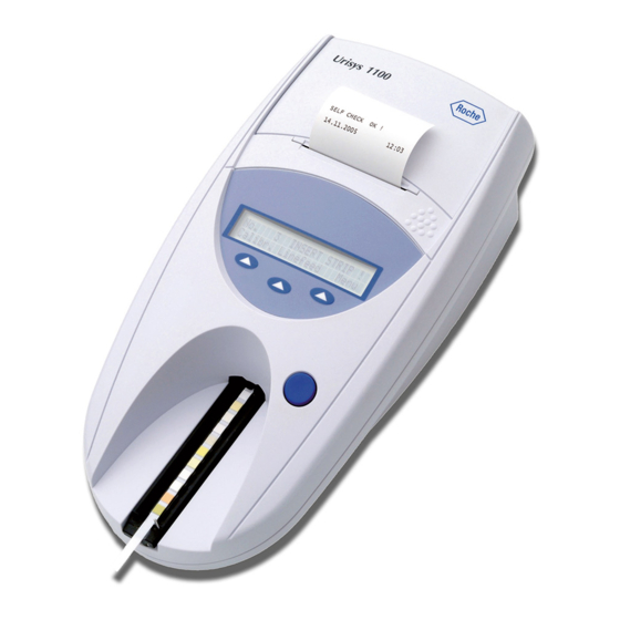
Components and Functions Component Function 1. Printer cover Flips up for insertion of printer paper 2. Display/keypad LCD display and three function keys for menu-driven operation and interfacing with the user 3. Test strip tray Holds and anchors the strip 4. -
Page 37: Menu Structure (Flowchart)
Menu Structure (Flowchart) Pressing the START button confirms the setting, closes the submenu, and resumes Ready-to-Measure status. SW 5.x (International Version) SELF CHECK Op.ID=ON OPERATOR: ……. Enter Op.ID! PASSWORD: Op.ID=OFF Enter password! AUTH.=OFF PASSWORD=O.K. No.: … INSERT STRIP ! Ready-to-Measure Status Calibr. - Page 38 Menu Structure (continued) Pressing the START button confirms the setting, closes the submenu, and resumes Ready-to-Measure status. SW 5.x (International Version) SETUP 1 Modes Strip Setup2 STRIP SETTINGS SETUP 2 Type Units Limits Date/Time Par. Setup3 STRIP TYPE:COMBUR10 UX DD.MM.YYYY hh:mm C-10 Sequence...
-
Page 39: Menu Functions
Menu Functions Self Check: During Self Check at power-on, the analyzer automatically checks that the program chip, the tray transport mechanism, the printer connection and optical system are all OK. The tray type is checked (see Sections 4 and 7.1) to en- sure that it correctly matches the strip type selected in the menu. - Page 40 Units: Options are: • Conventional units (mg/dL) • SI units (mmol/L) • Arbitrary units (1+, 2+, 3+, 4+) Either single units or combined units (conventional/arbitrary or SI/arbitrary) can be selected. The operator selects a unit in which the results are to be stored, printed and/or transferred to a computer. After a new unit has been selected, the repeat printout (activated by “Print Results”) and all following printouts and/or data transfer (acti- vated by “Send Results”) will be in the newly chosen unit.
-
Page 41: Results Table
Results Table The Urisys 1100 system prints the results in the following gradation of concentration: ATTENTION: For full details on how to interpret results, consult the following Roche Diagnostics publication, Compendium Urinalysis with Test Strips. Parameter Conventional Units SI Units Arbitrary Units (Conv.) -
Page 42: Changing The Range Limits
Changed range limits apply only to the test strip type for which the changes are made. CAUTION: The correctness of results obtained after the user has altered the ranges or reflectance values is not warranted by Roche Diagnostics. The user is responsible for validating the consistency of results after changes have been made. - Page 43 “Self Check OK” is executed with date and time; this happens whenever the instrument is switched on. If an error occurs, consult the Operator’s Manual or contact your local Roche Diagnostics service representative. Gebrauchsanweisung V04 / Operator’s Manual V04 / Manual de instrucciones V04...
-
Page 44: Modification For Combur 7 Test And Combur 5 Test Test Strips
(6) Upon first use of the analyzer, the message “REPEAT CALIBRATION” appears after a successful self check. Press the “No” key to attain Ready-to-Measure status. This also happens if the instrument is not used for more than seven days. To bring the instrument to Ready-to-Measure mode, insert the paper and execute the calibration. -
Page 45: Authentication
ATTENTION: If the maximum length of identification is exceeded the input cursor will skip to the first character and the identification will be overwritten. Authentication It is possible to download up to 300 operator IDs with corresponding passwords (up to 12 alphanumeric characters) from the host PC via the ASTM protocol. -
Page 46: Calibration
CAUTION: Regular calibration is necessary to ensure the quality of the results obtained. Roche Diagnostics cannot warrant the correctness of results if the system is not calibrated regularly. ATTENTION: You can recalibrate the system at any time, even if a week has not elapsed since the last calibration, for example if a Combur Test UX test strip has returned an implausible result. -
Page 47: Reading Test Strips
Calibration printout If the new calibration results are within the permitted range, the message “CALIBRATION O.K. ” is automatically printed with a date and timestamp and also a list of reflectance values for measuring positions 1–11 for the orange LED (middle column) and green LED (right column) (see Figure 8). -
Page 48: Patient Report
ATTENTION: To ensure that urinalysis is carried out correctly, read the package insert included with the test strips. 1. Dip the test strip in the urine sample and carefully wipe off any excess urine. Briefly (approximately 1 second) dab the side edge of the strip on a clean, absorbent surface (for example kitchen roll) (see Figure 9). -
Page 49: Strip Measurement Error
2. When Fast Mode is selected, the analyzer continues to operate in Fast Mode for the rest of the calendar day, even if the analyzer is switched off and then on again. 3. Fast Mode is cancelled as soon as the date is automatically incremented. WARNING: When performing serial measurements in Fast Mode, allow the strips to react for approxi- mately 45 seconds before inserting them in the Urisys 1100 system and pressing START. -
Page 50: Data Transmission To A Pc Or Host Computer
When data are entered from the keyboard, each character appears immediately in the display. It can be erased by back- spacing, and corrected as necessary. Press the keyboard ENTER key to terminate input, otherwise the Urisys 1100 system cannot start reading. Press the keyboard Escape key to delete the entire entry or turn the Urisys 1100 system off and then on again. -
Page 51: Error Messages And Troubleshooting
Error messages are shown in the display but are not printed out. Following 5 minutes of inactivity, the analyzer switches to Standby mode. The error message is displayed again when the START button is pressed. In the event that the instrument is defective, contact your local Roche Diagnostics representative. E1 REFERENCE PAD ERROR Cause: The middle portion of the reference pad on the tray is soiled or damaged. - Page 52 E6 CHIP ERROR ! Cause: The program chip on the right of the analyzer underneath the printer cov- er (see Figure 18) is missing, is not making contact, is defective or contains an old soft ware version. Action: Switch off the Urisys 1100 system. Insert the program chip and switch the instrument on again.
- Page 53 E18 INVALID OP.ID! Cause: The entered operator ID is not valid. Action: Enter a valid operator ID. E19 LIST DOWNLOAD FAILED Cause: The new operator ID list download failed. Action: No action. After 2 seconds next state starts with old list if there was. E20 NO VALID LIST! Cause: There is no valid list at all in the device.
-
Page 54: Connecting To Other Devices
This is not an RS 232 type interface. On request, Roche Diagnostics can supply a suitable standard data cable (see also Section 11). The connected PC must satisfy the requirements with regard to electrical safety laid down in EN 60950. -
Page 55: Technical Information And Notices
If a barcode reader and an external keyboard have to be connected a data cable CAB 322 IBM AT/XT DIN is needed. For questions regarding the operation of the Urisys 1100 system with barcode readers, please contact your local Roche Diagnostics representative. -
Page 56: Safety Notices
10.2 Safety Notices This analyzer was designed and manufactured to comply with the following international regulations “Safety requirements for electrical equipment for measurement, control and laboratory use” and left the factory in a safe condition. In order to keep the instrument in a perfect and safe condition, it is up to the user to observe all instructions and warnings included in this manual. -
Page 57: Ordering Information
11. Ordering Information The analyzer, consumables and accessories are: Catalogue No. (REF) 03 617 548 Content: Urisys 1100 analyzer, Adapter Model SA 125A-0735U-S, 100 V - 240 V, 50/60 Hz, Program Chip, Test Strip Trays C and N, Printer Paper, Operator’s Manual, Quick Reference Guide, power cable, Interactive Training CD. 03 666 735 Test strip tray Type C for Combur Test UX test strips... -
Page 58: Alphabetical Index
12. Alphabetical Index Section Section Acoustic signal (beep) Operating parts Barcode reader Parameters in patient report, setup Basic settings Pat. Id. entry Beep (acoustic signal) Patient identification Positioning hole Positioning of test strip Power supply 4.,10.1 Cable configuration Printer paper Calibration 4., 4.1, 5. - Page 59 Indice Página Introducción Descripción del sistema Principio de medición Componentes y funciones Software Resumen Estructura del menú (diagrama) Funciones del menú Tabla de resultados Modificación de los rangos Puesta en marcha Cambio a la medición de las tiras reactivas Combur Test o Combur Test Código de identificación del operador...
- Page 60 Test UX, Combur Test y Combur Test* de Roche Diagnostics. Las tiras reactivas son leídas y medidas bajo condiciones estándar, los resultados memorizados y enviados a la impresora incorporada al aparato y/o al interfaz serial. El sistema Urisys 1100 está destinado al uso como Diagnóstico In Vitro (IVD) por médicos y personal de laboratorio cualifi- cados.
- Page 61 2. Descripción del sistema Principio de medición La tira reactiva se deposita sobre una guía, y un motor de avance gradual la desplaza bajo el cabezal de lectura que per- manece estacionario. El aparato efectúa la medición tanto de la zona de referencia de la guía como de las distintas zonas de la tira reactiva.
- Page 62 Componentes y funciones Componente Función 1. Tapa de la impresora Puede levantarse para colocar el papel de impresora 2. Pantalla/teclado Pantalla de cristal líquido y tres teclas de función para la operación del menú y el interfaz con el usuario 3.
- Page 63 Estructura del menú (diagrama) Pulsando la tecla START, Vd. confirma el ajuste, cierra el submenú y retorna al estado “Listo para medición”. SW 5.x (Versión internacional) AUTOCONTROL Cod. Op.=ON OPERADOR: ……. Entrar nuevo COD. OP.! PASSWORD: Cod. Op.=OFF Entrar password ! AUTH=OFF PASSWORD=O.K.
- Page 64 Estructura del menú (Continuación) Pulsando la tecla START, Vd. confirma el ajuste, cierra el submenú y retorna al estado “Listo para medición”. SW 5x (Versión internacional) SETUP 1 Modo Tira Setup2 AJUSTES DE TIRA SETUP 2 Tipo Unidad Limites Fecha/Hora Par.
- Page 65 Funciones del menú Autocontrol: Tras el encendido, el aparato prueba mediante un autocontrol automático que el chip de programa, el meca- nismo de accionamiento de la guía, la conexión de impresora y el sistema óptico funcionan perfectamente. Al mismo tiem- po se comprueba el tipo de guía (ver apartados 4 y 7.1) para garantizar que se corresponde con el tipo de tiras selecciona- das en el menú.
- Page 66 Tipo de tira reactiva: Selección del tipo de tira reactiva: • Combur Test UX (“C-10”) • Combur Test (“C-7”) • Combur Test (“C-5”) El sistema Urisys 1100 ha sido ajustado en fábrica para la medición de las tiras reactivas Combur Test UX.
- Page 67 Fecha/hora: Ajuste de fecha y hora. El aparato ha sido ajustado en fábrica siguiendo el orden día-mes-año, y la hora en horas y minutos (conforme a periodos de 24 horas). No obstante, la hora también puede ser mostrada siguiendo el sistema “12 horas más a.m./p.m”. Pulse la te- cla de función “Secuencia”...
- Page 68 Tabla de resultados El sistema Urisys 1100 imprime los resultados en los niveles de concentración siguientes: ATENCIÓN: Para obtener más detalles sobre cómo interpretar los resultados, consulte el siguiente folleto de Roche Diagnostics: Compendium Urinalysis with Test Strips. Parámetro Unidades convencionales...
- Page 69 ATENCIÓN: Por favor, controle inmediatamente la integridad del contenido de la caja. En caso de comprobar daños de transporte en el contenido, diríjase al representante local de Roche Diagnostics. Contenido: •...
- Page 70 Si ocurre un error, consulte el Manual del Operador o diríjase al re- presentante local de Roche Diagnostics. Gebrauchsanweisung V04 / Operator’s Manual V04 / Manual de instrucciones V04...
- Page 71 (6) Al poner el aparato en marcha por primera vez y tras llevar a cabo el autocontrol sin detectar errores, en la pantalla aparece el mensaje “REPETIR CALIBRACIÓN” (REPEAT CALIBRATION). Pulse ahora la tecla “No” y el aparato pasará al modo “Listo para medición”. Esto también ocurre si el aparato no ha sido utilizado durante más de siete días.
- Page 72 ATENCIÓN: Si se supera la longitud máxima de identificación el cursor de entrada saltará al primer carác- ter y se sobreescribirá la identificación. Autenticación Es posible descargar hasta 300 códigos de identificación del operador con las respectivas contraseñas (hasta 12 caracte- res alfanuméricos) desde el servidor vía el protocolo ASTM.
- Page 73 8). Retire la tira reactiva y deséchela correctamente (siguiendo las instrucciones del prospecto de la tira reactiva). ADVERTENCIA: La calibración regular es necesaria para asegurar la calidad de los resultados obtenidos. Roche Diagnostics no puede garantizar la exactitud de los resultados si el sistema no es calibrado regularmente.
- Page 74 ATENCIÓN: Si contesta “No” a la invitación semanal “REPETIR CALIBRACIÓN”, por ejemplo porque ha consumido sus reservas de tiras de calibración Control-Test M, el mensaje “Repetir calibración” es impreso junto con cada informe de paciente de mediciones subsiguientes. Obtenga un nuevo paquete de Control-Test M y proceda inmediatamente a la recalibración.
- Page 75 6. Medición de las tiras reactivas Resumen El sistema Urisys 1100 es sumamente fácil de manejar. Simplemente introduzca la tira reactiva cuando la pantalla le mues- tre el número de la muestra (ver apartado 6.2), y pulse la tecla START para comenzar la medición. El aparato dispone de dos modos de operación distintos para llevar a cabo mediciones: 1.
- Page 76 ATENCIÓN: Asegúrese de que el estribo de sujeción encaja en su sitio y que la tira reactiva se encuentra en la posición correcta. Si la tira reactiva no está colocada correctamente en el centro de la guía, mué vala con cuidado hasta que se encuentre en su sitio (ver figura 14). Ponga atención a no tocar la guía. 4.
- Page 77 Errores de medición Si en la pantalla aparece el mensaje de error “ERROR DE MEDICIÓN”; probablemente ha cometido Ud. un error en la apli- cación de la tira reactiva o del aparato. Consulte el capítulo 8 para más detalles. Introducción del código de identificación del paciente, código de identificación del operador y contraseña de autenticación Código de identificación del paciente Cuando el aparato esté...
- Page 78 Si opera con un interfaz bidireccional, sólo podrá transferir los resultados mediante la opción “Enviar” del menú “MEMORIA”. De no conseguir establecer la comunicación bidireccional entre el ordenador personal y el central, el sistema Urisys 1100 interrumpe la transferencia tras algunos intentos y muestra en pantalla el mensaje “ERROR INTERFAZ” (ver apartado 8).
- Page 79 Los mensajes de error aparecen en pantalla pero no se imprimen. Transcurridos cinco minutos sin pulsar tecla alguna, el aparato pasa al modo standby. El mensaje de error aparece de nuevo en la pantalla al pulsar la tecla START. En caso de que el aparato esté defectuoso, diríjase al representante local de Roche Diagnostics. E1 ERROR ZONA DE Causa: El escalon medio de la zona de referencia gris de la guía está...
- Page 80 E4 ERROR DE CALIBRACIÓN ! Causa: Los valores de calibración difieren de los obtenidos en la última calibra- ción válida. Medida: Pulse la tecla START. Repita la calibración con una nueva tira de cali- bración del estuche de Control-Test M. Asegúrese de que la tira encaja correcta- mente en el estribo de sujeción (ver apartado 5).
- Page 81 E12 ERROR ÓPTICO ! Causa: O bien falta la zona de referencia de la guía, o un diodo fotoemisor o el detector han sido deteriorados. Medida: Coloque la zona de referencia o utilice la guía de reserva. Pulse la tecla START.
- Page 82 (ver el lector recomendado) o de un teclado AT/PC, por ej. el teclado Reflotron de Roche Diagnostics (en Informacio- nes para el pedido, apartado 11).
- Page 83 CAB 322 IBM AT/XT DIN. Para cualquier pregunta relacionada con el funcionamiento del sistema Urisys 1100 con lectores de código de barras, dirí- jase al representante local de Roche Diagnostics. 10. Datos técnicos y advertencias 10.1 Datos técnicos...
- Page 84 10.2 Indicaciones de seguridad Además, este aparato fue diseñado y manufacturado para cumplir con las disposiciones internacionales “Normas de segu- ridad para equipos eléctricos de medición, control y de laboratorio”, y ha salido de fábrica en perfecto estado respecto a la seguridad.
- Page 85 11. Informaciones para el pedido El aparato, los artículos de consumo y los accesorios son: de Cat. (REF) 03 617 548 Contenido: Aparato Urisys 1100, Adaptador SA 125A-0735U-S, 100 V - 240 V, 50 - 60 Hz, chip de programa, guía para tiras reactivas C y N, papel para impresora, manual de instrucciones, guía de referencia rápida, cable de alimentación, CD de formación interactiva.
- Page 86 12. Registro alfabético Apartado Apartado Ajuste de la impresora Medición de tiras reactivas Ajuste del dato Memoria Ajustes de base Mensaje de pantalla 3.2, 8. Artículos de consumo y accesorios, pedir Mensajes de error Autocontrol Modo Standby Avance del papel 3.3, 4.
-
Page 87: Garantiekarte
13. Garantiekarte/Warranty Card/Certificado de garantia Urisys 1100 Garantiekarte / Warranty Card Serien-Nr. Serial No. Name, Anschrift, Tel.-Nr. des Käufers Buyer’s name, address and tel. no. Kaufdatum: Stempel und Unterschrift des Händlers Date of purchase: Stamp and signature of dealer Urisys 1100 Certificado de garantía N°... -
Page 89: Adressenliste
14. Adressenliste/International addresses/Lista de direcciones Argentina Chile Productos Roche S.A.Q. e I. Productos Roche Ltda., División Diagnóstica Avda. Quilín 3750 Av. Belgrano 2350, Macul, Santiago Don Torcuato Buenos Aires Chile República Argentina Phone: +56 2 4413200 Phone: +54 11 5129-8000... - Page 90 Fax: +852 2418 0728 Roche Diagnostics Nederland BV Transistorstraat 41 India 1322 CK Almere Roche Diagnostics India (Pvt ) Ltd. Nederland 761, Solitaire Corporate Park, Phone: +31 36 53 94 911 167, Har Govindji Marg, Chakala, Fax: +31 36 53 94 202...
- Page 91 Philippines Fax: +421 7 54 78 85 12 Phone: +63 2 893 45 67 South Africa fax: +63 2 893 06 17 Roche Products (Pty) Ltd - South Africa Poland Diagnostics Division 9 Will Scarlet Road/Ferndale Roche Diagnostics Polska Sp.z.o.o.
- Page 92 South Korea United Kingdom Roche Diagnostics Korea Co., Ltd Roche Diagnostics Ltd 15th Floor, Sam-Wha Building, 144/17, Samsung-dong, Charles Avenue Kangnam-Ku Burgess Hill, RH15 9RY 135-092 Seoul United Kingdom Republic of Korea Phone: +44 1444 256000 Phone: +82 2 550 3300...
- Page 94 Roche Diagnostics GmbH D-68298 Mannheim Germany www.diavant.com www.roche-diagnostics.com...
Need help?
Do you have a question about the cobas Urisys 1100 and is the answer not in the manual?
Questions and answers