Table of Contents
Advertisement
Quick Links
Advertisement
Table of Contents

Related Manuals for Alfa Laval SolidC Series


Summary of Contents for Alfa Laval SolidC Series
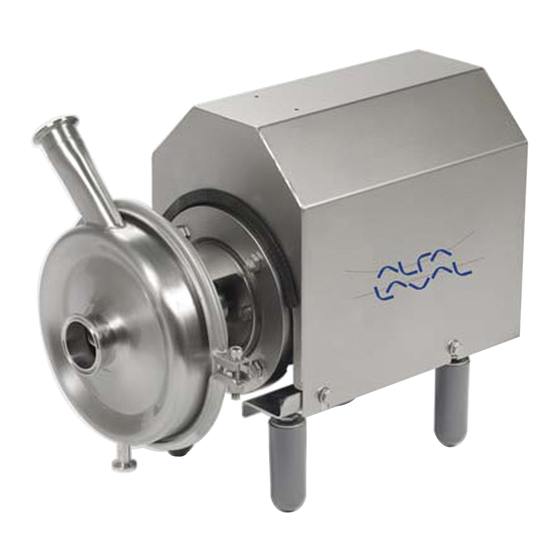
- Page 1 Instruction Manual SolidC Pump ESE00797-EN3 2010-02 Original manual...
-
Page 2: Table Of Contents
Table of contents The information herein is correct at the time of issue but may be subject to change without prior notice 1. EC Declaration of Conformity ............... 2. Safety ....................2.1. Important information ................2.2. Warning signs ..................2.3. Safety precautions ................3. -
Page 3: Ec Declaration Of Conformity
- Low Voltage Directive 2006/95/EC - EMC Directive 2004/108/EC - Machinery Directive 2006/42/EC The technical construction file is retained at the above address Manager, Product center Fluid Handling Bjarne Søndergaard Title Name Alfa Laval Kolding Company Signature Designation... -
Page 4: Safety
2 Safety Unsafe practices and other important information are emphasized in this manual. Warnings are emphasized by means of special signs. Always read the manual before using the pump! 2.1 Important information WARNING Indicates that special procedures must be followed to avoid severe personal injury. CAUTION Indicates that special procedures must be followed to avoid damage to the pump. -
Page 5: Safety Precautions
2 Safety Unsafe practices and other important information are emphasized in this manual. Warnings are emphasized by means of special signs. Always read the manual before using the pump! 2.3 Safety precautions Installation: Always read the technical data thoroughly. (See chapter 6 Technical data) Always use a lifting crane when handling the pump. -
Page 6: Installation
The instruction manual is part of the delivery. Study the instructions carefully. The standard delivery does not include the test certificate. This can be supplied on request. The large pump sizes are very heavy. Alfa Laval therefore recommends the use of a lifting crane when handling the pump. 3.1 Unpacking/Delivery... -
Page 7: Installation
Study the instructions carefully and pay special attention to the warnings! Always check the pump before operation. - See pre-use check in section 3.3 Pre-use check, page 9 The large pump sizes are very heavy. Alfa Laval therefore recommends the use of a lifting crane when handling the pump. 3.2 Installation... -
Page 8: Pre-Use Check
- At end of use, the equipment shall be recycled according to relevant, local regulations. Beside the equipment itself, any hazardous residues from the process liquid must be considered and dealt with in a proper manner. When in doubt, or in the absence of local regulations, please contact the local Alfa Laval sales company. -
Page 9: Operation
Study the instructions carefully and pay special attention to the warnings! The pump is fitted with a warning label indicating correct throttling. 4.1 Operation/Control Step 1 CAUTION Alfa Laval cannot be held responsible for incorrect operation/control. Always read the technical data thoroughly. (See chapter 6 Technical data) Step 2... - Page 10 4 Operation Study the instructions carefully and pay special attention to the warnings! The pump is fitted with a warning label indicating correct throttling. Step 6 Throttling! Control: Reduce the capacity and the power consumption by means of: - Throttling the pressure side of the pump. - Reducing the impeller diameter.
-
Page 11: Fault Finding
4 Operation Pay attention to possible faults. Study the instructions carefully. 4.2 Fault finding NOTE! Study the maintenance instructions carefully before replacing worn parts. - See section 5.1 General maintenance Problem Cause/result Remedy - Pumping of viscous liquids - Larger motor or smaller impeller Overloaded motor - Pumping of liquids with high density - Low outlet pressure (counter pressure) - Higher counter pressure (throttling) -
Page 12: Recommended Cleaning
4 Operation The pump is designed for cleaning in place (CIP). CIP = Cleaning In Place. Study the instructions carefully and pay special attention to the warnings! NaOH = Caustic Soda. HNO3 = Nitric acid. 4.3 Recommended cleaning Step 1 Caustic danger! Always handle lye and acid with great care. -
Page 13: Maintenance
5 Maintenance Maintain the pump carefully. Study the instructions carefully and pay special attention to the warnings! Always keep spare shaft seals and rubber seals in stock. See separate motor instructions. 5.1 General maintenance Step 1 NOTE All scrap must be stored/discharged in accordance with current rules/directives. - Page 14 5 Maintenance Maintain the pump carefully. Study the instructions carefully and pay special attention to the warnings! Always keep spare shaft seals and rubber seals in stock. See separate motor instructions. Motor bearings Shaft seal Rubber seals Preventive maintenance Replace after 12 months: Replace when replacing the (one-shift) Complete shaft seal shaft seal...
-
Page 15: Dismantling Of Pump/Shaft Seals
5 Maintenance Study the instructions carefully. The items refer to the parts list and service kits section. Handle scrap correctly. * : Relates to the shaft seal. 5.2 Dismantling of pump/shaft seals Step 1 Remove screws, spring washers, clamps (55) and pump casing (29). - Page 16 5 Maintenance Study the instructions carefully. The items refer to the parts list and service kits section. Handle scrap correctly. * : Relates to the shaft seal. Step 6 1. Remove the stationary seal ring (11). Use the tool 2. Remove the O-ring (12) from stationary seal ring (11). supplied Left hand thread Step 7...
-
Page 17: Assembly Of Pump/Single Shaft Seal
5 Maintenance Study the instructions carefully. The items refer to the parts list and service kits section. Handle scrap correctly. * : Relates to the shaft seal. 5.3 Assembly of pump/single shaft seal Step 1 1. Remove spring (13). 2. Lubricate O-ring (15) and fit it in rotating seal ring (14). NOTE! Make sure that O-ring (15) has max. - Page 18 5 Maintenance Study the instructions carefully. The items refer to the parts list and service kits section. Handle scrap correctly. * : Relates to the shaft seal. Step 7 1. Lubricate O-ring (38) and fit it in impeller (37). 2. Lubricate impeller hub with silicone grease or oil. 3.
-
Page 19: Assembly Of Pump/Flushed Shaft Seal
5 Maintenance Study the instructions carefully. The items refer to the parts list and service kits section. Lubricate the rubber seals before fitting them. * : Relates to the shaft seal. 5.4 Assembly of pump/flushed shaft seal Step 1 Use the tool supplied 1. - Page 20 5 Maintenance Study the instructions carefully. The items refer to the parts list and service kits section. Lubricate the rubber seals before fitting them. * : Relates to the shaft seal. Step 7 Lubricate O-ring (26) and slide it onto back plate (25). TD 241-028/1 Step 8 1.
-
Page 21: Adjustment Of Shaft
5 Maintenance Study the instructions carefully. The items refer to the parts list and service kits section. Lubricate the rubber seals before fitting them. * : Relates to the shaft seal. 5.5 Adjustment of shaft Step 1 1. Loosen screws (61). 2. -
Page 22: Technical Data
6 Technical data It is important to observe the technical data during installation, operation and maintenance. Inform the personnel about the technical data. 6.1 Technical data Data Max. inlet pressure 400 kPa (4 bar) Temperature range C to +120 C (EPDM) Materials Product wetted steel parts AISI 316L... - Page 23 6 Technical data It is important to observe the technical data during installation, operation and maintenance. Inform the personnel about the technical data. Tightening torques Below table specifies the tightening torques for the screws, bolts and nuts in this pump. Always use below torques if no other values are stated.
-
Page 24: Parts List And Service Kits
7 Parts list and Service Kits The drawing shows SolidC pump, sanitary version. The items refer to the parts lists in the following sections 7.1 Drawing US legs are different to the ones shown. For further information see Spare Parts catalogue. Impeller screw Flushed shaft seal Fitting of back plate... -
Page 25: Solidc-1
7 Parts list and Service Kits The drawing shows SolidC pump, sanitary version. The items refer to the parts lists in the following sections 7.2 SolidC-1 FSS = Flushed Shaft Seal 13 15 22 17 TD 241-044 20 21... - Page 26 7 Parts list and Service Kits The drawing shows SolidC pump, sanitary version. The items refer to the parts lists in the following sections Parts list Service kits Denomination C/SIC SIC/SIC Pos. Denomination Service kit for single shaft seal Tool for seal Service kit, EPDM.
-
Page 27: Solidc-2
7 Parts list and Service Kits The drawing shows SolidC pump, sanitary version. The items refer to the parts lists in the following sections 7.3 SolidC-2 FSS = Flushed Shaft Seal 13 15 22 17 TD 241-044 20 21... - Page 28 7 Parts list and Service Kits The drawing shows SolidC pump, sanitary version. The items refer to the parts lists in the following sections Parts list Service kits Denomination C/SIC SIC/SIC Pos. Denomination Service kit for single shaft seal Tool for seal Service kit, EPDM.
-
Page 29: Solidc-3
7 Parts list and Service Kits The drawing shows SolidC pump, sanitary version. The items refer to the parts lists in the following sections 7.4 SolidC-3 FSS = Flushed Shaft Seal 18 19 43 44 10 45 22 17 TD 241-002... - Page 30 7 Parts list and Service Kits The drawing shows SolidC pump, sanitary version. The items refer to the parts lists in the following sections Parts list Service kits Denomination C/SIC SIC/SIC Pos. Denomination Service kit for single shaft seal Tool for seal Service kit, EPDM.
-
Page 31: Solidc-4
7 Parts list and Service Kits The drawing shows SolidC pump, sanitary version. The items refer to the parts lists in the following sections 7.5 SolidC-4 FSS = Flushed Shaft Seal 18 19 43 44 10 45 22 17 TD 241-002... - Page 32 7 Parts list and Service Kits The drawing shows SolidC pump, sanitary version. The items refer to the parts lists in the following sections Parts list Service kits Denomination C/SIC SIC/SIC Pos. Denomination Service kit for single shaft seal Tool for seal Service kit, EPDM.
-
Page 33: Solidc 1-4, Shaft Seal
7 Parts list and Service Kits The drawing shows SolidC pump, sanitary version. The items refer to the parts lists in the following sections 7.6 SolidC 1-4, Shaft Seal Single shaft seal Flushed shaft seal TD 241-091... - Page 34 7 Parts list and Service Kits The drawing shows SolidC pump, sanitary version. The items refer to the parts lists in the following sections Parts list Pos. Denomination Complete shaft seal Complete shaft seal ♦ Complete shaft seal Complete shaft seal Stationary seal ring O-ring Spring...
Need help?
Do you have a question about the SolidC Series and is the answer not in the manual?
Questions and answers