Sign In
Upload
Download
Table of Contents
Contents
Add to my manuals
Delete from my manuals
Share
URL of this page:
HTML Link:
Bookmark this page
Add
Manual will be automatically added to "My Manuals"
Print this page
×
Bookmark added
×
Added to my manuals
Manuals
Brands
Vecow Manuals
Computer Accessories
SPC-7000
User manual
Vecow SPC-7000 User Manual
Intel core i7/i5/i3 (tiger lake) ultra-compact fanless embedded system 1 gige lan, 1 2.5g gige lan, 10g usb, 2 com, 9v to 55v
Hide thumbs
1
2
3
4
5
Table Of Contents
6
7
8
9
10
11
12
13
14
15
16
17
18
19
20
21
22
23
24
25
26
27
28
29
30
31
32
33
34
35
36
37
38
39
40
41
42
43
44
45
46
47
48
49
50
51
52
53
54
55
56
57
58
59
60
61
62
63
64
65
66
67
68
69
70
71
72
73
74
75
76
77
78
79
80
81
82
83
84
85
86
87
88
89
90
91
92
93
94
95
96
97
98
99
100
101
102
103
104
105
106
page
of
106
Go
/
106
Contents
Table of Contents
Bookmarks
Table of Contents
Table of Contents
Chapter 1 General Introduction
Overview
Features
Product Specification
Specifications of SPC-7000
Specifications of SPC-7100
Specifications of SPC-7200
Supported CPU List
Mechanical Dimension
SPC-7000 Mechanical Drawing
SPC-7100 Mechanical Drawing
SPC-7200 Mechanical Drawing
Chapter 2 Getting to Know Your Spc-7000
SPC-7000/7100/7200 Packing List
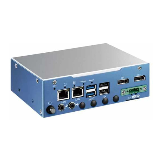
Front Panel I/O & Functions
Rear Panel I/O & Functions
Connector/Jumper Locations
Main Board Jumper Settings
Ignition Control
Chapter 3 System Setup
How to Open Your SPC-7000
Installing DDR4 SO-DIMM Module
Installing
Installing SSD/HDD
Installing SIM Card
Installing Antenna Cable
Mounting Your SPC-7000
Advertisement
Quick Links
1
Specifications of Spc-7000
2
Front Panel I/O & Functions
Download this manual
SPC-7000/7100/7200
Intel
®
Core™ i7/i5/i3 (Tiger Lake) Ultra-Compact Fanless Embedded System
1 GigE LAN, 1 2.5G GigE LAN, 10G USB, 2 COM, 9V to 55V, -40°C to 75°C
USER
USER
Manual
Manual
1.0.0 Edition 20210329
Table of
Contents
Previous
Page
Next
Page
1
2
3
4
5
Advertisement
Table of Contents
Need help?
Do you have a question about the SPC-7000 and is the answer not in the manual?
Ask a question
Questions and answers
Related Manuals for Vecow SPC-7000
Computer Accessories Vecow SPC-7100 User Manual
Intel core i7/i5/i3 (tiger lake) ultra-compact fanless embedded system 1 gige lan, 1 2.5g gige lan, 10g usb, 2 com, 9v to 55v (106 pages)
Computer Accessories Vecow SPC-7100- 1145G7E User Manual
Intel core i7/i5/i3 (tiger lake) ultra-compact fanless embedded system 1 gige lan, 1 2.5g gige lan, 10g usb, 2 com, 9v to 55v (106 pages)
This manual is also suitable for:
Spc-7100
Spc-7200
Spc-7000-1185g7e
Spc-7000-1145g7e
Spc-7100-1185g7e
Spc-7100- 1145g7e
...
Show all
Spc-7200 1185g7e
Spc-7200-1145g7e
Table of Contents
Print
Rename the bookmark
Delete bookmark?
Delete from my manuals?
Login
Sign In
OR
Sign in with Facebook
Sign in with Google
Upload manual
Upload from disk
Upload from URL


Need help?
Do you have a question about the SPC-7000 and is the answer not in the manual?
Questions and answers