Advertisement
Quick Links
Advertisement

Related Manuals for Wilson Electronics 311230


Summary of Contents for Wilson Electronics 311230
- Page 1 Installation Guide Drive RV Antenna...
-
Page 2: Table Of Contents
Index Package Contents . . . . . . . . . . . . . . . . . . . . . . . . . . . . . . . . . . . . . . . . . . . . . . . . . . . . . . . . . . . . 1 Select Mounting Location . -
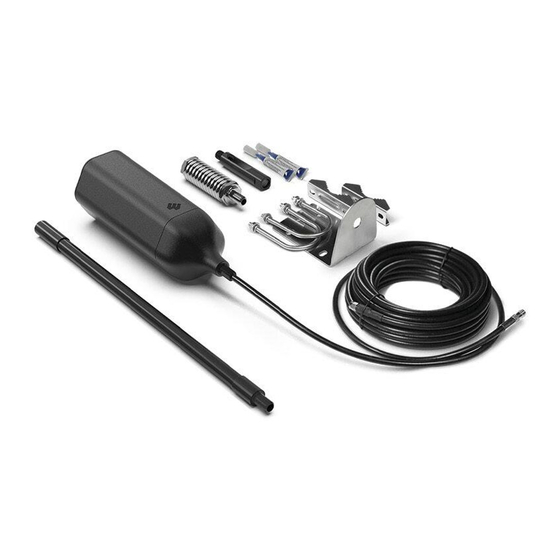
Page 3: Package Contents
Package Contents 13 in . Mast Spring, Side Exit Thread Lock Drive RV Antenna Extension Adapter & Antenna w/25 ft . Cable Mount (311230) -
Page 4: Select Mounting Location
Select Mounting Location common outside antenna location Mount Outside Antenna to a ladder or pole, so that the entire Outside Antenna is above the roof line of the RV and clear of other metal obstructions . We recommend doing a ‘soft install’, verifying the system works as desired, before permanently installing the kit . -
Page 5: Assemble The Antenna
Assemble the Antenna Once you have determined the best location for the antenna, insert cable through mast(s) then through Side Exit Adpater . 13 in. 13 in. mast mast cable from antenna Side Exit Adapter run cable through Mast Extension(s) Antenna Spring Mast Extension... - Page 6 (Assemble the Antenna cont .) Use thread locker (provided) to thread Drive OTR Antenna points and screw into place . NOTE: Be sure the antenna is the correct height before applying thread locker . NOTE: When adding the side exit adapter hold the antenna vertically and screw the adapter from the bottom up .
-
Page 7: Mounting The Antenna
Mounting the Antenna Side Exit Mount to ladder rail on RV as shown Adapter and route cable into RV then connect cable to the booster . The system add thread locker performs best with maximum vertical and horizontal separation . Spring (optional) NOTE: If installing with Spring, the... -
Page 8: Safety Guidelines & Specifications
Half-Power Azimuth Beamwidth (°) Half-Power Elevation Beamwidth (°) Impedance (Ω) Maximum Power (W) Mechanical Specifications Model 311230 Connector SMA (F) Dimensions (in / mm) 7 .422 x 2 .688 / 188 x 68 Weight (lb / kg) .40 / 0 . 1 81... -
Page 9: Warranty
Returned Material Authorization (RMA) number supplied by Wilson Electronics . Wilson Electronics shall, at its option, either repair or replace the product . Wilson Electronics will pay for delivery of the repaired or replaced product back to the original consumer if located within the continental U .S . - Page 10 Notes 1 .866 .294 . 1 660 www .wilsonelectronics.com support@wilsonelectronics .com...
- Page 11 Notes 1 .866 .294 . 1 660 www .wilsonelectronics.com support@wilsonelectronics .com...
- Page 12 866 .294 . 1 660 www .wilsonelectronics .com support@wilsonelectronics .com Copyright © 2020 Wilson Electronics . All rights reserved . Wilson Electronics products covered by U .S . patent(s) and pending application(s) For patents go to: weboost .com/us/patents GDE000300_Rev01_08 . 1 0 .20...
Need help?
Do you have a question about the 311230 and is the answer not in the manual?
Questions and answers