Table of Contents
Advertisement
Quick Links
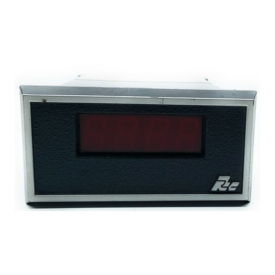
MODEL APLSP - APOLLO SLAVE DISPLAY
3, 4, 5, OR 6-DIGIT, 0.56" (14.2 mm) HIGH LED DISPLAY
!
3, AND 5-DIGIT UNITS HAVE A "-" SIGN
!
FULL PARALLEL OR STROBED BCD
!
SELECTABLE 0 OR 1 TRUE LOGIC FOR BOTH DATA AND
!
STROBE INPUTS
DIP SWITCH SELECTABLE DECIMAL POINTS
!
OPTIONAL ACCESSORY BOARDS FOR CASCADING
!
EDGE-CARD INTERFACE
!
SEALED FRONT PANEL CONSTRUCTION (NEMA 4/IP65)
!
DESCRIPTION
The Apollo Slave Display converts numerical BCD data supplied by
equipment such as programmable controllers, into seven segment LED display
information. The Slave Display is available in 3, 4, 5 and 6 digit versions, in either
a 5 VDC or 10 to 28 VDC (3 and 5-digit versions have a "-" sign). The unit has
three DIP Switch selectable decimal points for displaying in 10ths, 100ths and
1000ths. Other DIP Switches allow selection of 0 or 1 true logic and pull-down or
pull-up resistors for both the Data and Strobe inputs. The unit can display the
numbers 0-9 by sending the corresponding BCD information. Individual digits
can be blanked by sending a Binary Code greater than 9. For the 3 and 5-digit
versions, the minus sign is activated by applying the selected logic true level to
the terminal marked "(-) sign" then strobing the terminal marked "(-) STR".
Four optional accessory boards provide terminal blocks for easy wire hook-
up and DIP sockets to cascade the BCD lines to other units. Models ATB1 (3
and 4-digit) and ATB3 (5 and 6-digit) contain all terminal block positions and
are used when hooking up one Slave Display or as the first in a series of
cascaded displays. Models ATB2 (3 and 4-digit) and ATB4 (5 and 6-digit) do
not have the terminal blocks for the 16 and 24 BCD data inputs. These boards
are available for use in cascaded systems where the ACA1 DIP Plug Cable
Assembly is used to connect the data inputs.
SAFETY SUMMARY
All safety related regulations, local codes and instructions that appear in the
manual or on equipment must be observed to ensure personal safety and to
prevent damage to either the instrument or equipment connected to it. If
equipment is used in a manner not specified by the manufacturer, the protection
provided by the equipment may be impaired.
CAUTION: Read complete instructions
prior to installation
and operation of the unit.
DIMENSIONS In inches (mm)
SPECIFICATIONS
1. POWER: Power supply must be Class 2 or SELV rated.
APLSP3A, APLSP4A: 5 VDC ±20% @ 200 mA max.
APLSP5A, APLSP6A: 5 VDC ±20% @ 235 mA max.
APLSP3B, APLSP4B: 10 to 28 VDC @ 200 mA max.
APLSP5B, APLSP6B: 10 to 28 VDC @ 235 mA max.
2. INPUT IMPEDANCE (ALL Inputs): 100 KΩ
3. INPUT TRIGGER LEVELS:
5 V Versions: V
10 to 28 V Version: V
4. CERTIFICATIONS AND COMPLIANCES:
SAFETY
ELECTROMAGNETIC COMPATIBILITY:
Immunity to EN 50082-2
Electrostatic discharge
Electromagnetic RF fields
Fast transients (burst)
RF conducted interference
Simulation of cordless telephone
Emissions to EN 50081-2
RF interference
Refer to the EMC Installation Guidelines section of this bulletin for
5. ENVIRONMENTAL CONDITIONS:
Operating Temperature: 0 to 50°C
Storage Temperature: -40 to 70°C
Operating and Storage Humidity: 85% max. relative humidity (non-
Altitude: Up to 2000 meters
6. CONSTRUCTION: This unit is rated for NEMA 4/IP65 indoor use.
Installation Category I, Pollution Degree 2
7. WEIGHT: 0.9 lbs (0.41 Kg)
Note: Recommended minimum clearance (behind the panel) for
mounting clip installation is 2.1" (53.3) H x 5.5" (140) W.
1
= 1.0 V, V
= 4.0 V, max. input voltage = 28 VDC
IL
IH
= 3.0 V, V
IL
IH
IEC 1010-1, EN 61010-1: Safety requirements for electrical equipment
for measurement, control, and laboratory use, Part 1.
IP65 Enclosure rating (Face only), IEC 529
Type 4 Enclosure rating (Face only), UL50
EN 61000-4-2 Level 2; 4 Kv contact
EN 61000-4-3 Level 3; 10 V/m
EN 61000-4-4 Level 4; 2 Kv I/O
EN 61000-4-6 Level 3; 10 V/rms
ENV 50204
EN 55011
additional information.
condensing) from 0°C to 50°C.
Bulletin No. APLSP4/6-I
Drawing No. LP0114
Released 1/05
= 10.0 V, max. input voltage = 28 VDC
Level 3; 8 Kv air
80 MHz - 1 GHz
Level 3; 2 Kv power
150 KHz - 80 MHz
Level 3; 10 V/m
900 MHz ± 5 MHz
200 Hz, 50% duty cycle
Enclosure class B
Power mains class B
PANEL CUT-OUT
Advertisement
Table of Contents

Related Manuals for red lion APLSP


Summary of Contents for red lion APLSP
- Page 1 Bulletin No. APLSP4/6-I Drawing No. LP0114 Released 1/05 MODEL APLSP - APOLLO SLAVE DISPLAY 3, 4, 5, OR 6-DIGIT, 0.56" (14.2 mm) HIGH LED DISPLAY 3, AND 5-DIGIT UNITS HAVE A “-” SIGN FULL PARALLEL OR STROBED BCD SELECTABLE 0 OR 1 TRUE LOGIC FOR BOTH DATA AND...
- Page 2 LOGIC TRUE SELECTION 4-DIGIT “FULL PARALLEL” CASCADED SYSTEM The Apollo Slave Display has four DIP switch positions used to set the unit to be compatible with the logic convention of the output device (programmable controller, etc.). DIP switch A (SWA) has two switch positions which provide pull-up (SNK) or pull-down (SRC) resistors on all Data and Strobe inputs.
-
Page 3: Dip Switch Positions
EMC Installation Guidelines 4-DIGIT “4-BIT MULTIPLEXED” CASCADED SYSTEM Although this unit is designed with a high degree of immunity to For 3-Digit Unit: ElectroMagnetic Interference (EMI), proper installation and wiring methods (-) SIGN - 8000 must be followed to ensure compatibility in each application. The type of the (-) STR - 1000’s STR electrical noise, source or coupling method into the unit may be different for various installations. - Page 4 TIMING SPECIFICATIONS FOR STROBE & DATA INPUTS EDGECARD CONNECTOR PIN-OUTS MODEL APLSP3A: “5 VDC VERSION” MODEL APLSP3B: “10 to 28 VDC VERSION” tws min. 5 µs (strobe pulse width) tdsu min. 1 µs (data set-up time) tdh min. 5 µs (data hold time) tcy min.
-
Page 5: Installation Environment
ACCESSORY BOARD POWER CONNECTIONS ACCESSORY BOARD INSTALLATION The DC power to the unit is applied between “V1” or “V2” and The optional accessory board (ATB) is mounted directly to the rear of the “COMMON” of Terminal Block A (TBA). The voltage applied to the Apollo Slave Display. -
Page 6: Troubleshooting
TROUBLESHOOTING For further technical assistance, contact technical support at the appropriate company numbers listed. ORDERING INFORMATION PART NUMBER AVAILABLE SUPPLY VOLTAGES MODEL NO. DESCRIPTION 5 VDC 10 to 28 VDC APLSP3 Apollo Slave Display 3-Digit APLSP3A0 APLSP3B0 APLSP4 Apollo Slave Display 4-Digit APLSP4A0 APLSP4B0 APLSP5... - Page 7 This page intentionally left blank...
-
Page 8: Limited Warranty
The Company disclaims all liability for any affirmation, promise or representation with respect to the products. The customer agrees to hold Red Lion Controls harmless from, defend, and indemnify RLC against damages, claims, and expenses arising out of subsequent sales of RLC products or products...