Table of Contents
Advertisement
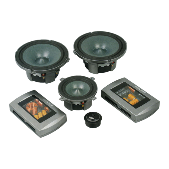
SPX-107R / SPX-137R / SPX-177R
COMPONENT 2-WAY SPEAKER SYSTEM
SPX-17MB
MIDBASS SPEAKER SYSTEM
OWNER'S MANUAL
Please read before using this equipment
ALPINE ELECTRONICS, INC.
Tokyo office ; 1-1-8 Nishi Gotanda,
Shinagawa-ku, Tokyo 141-8501, Japan
Tel.: (03) 3494-1101
ALPINE ELECTRONICS OF AMERICA, INC.
19145 Gramercy Place, Torrance,
California 90501, U.S.A.
Tel.: 1-800-ALPINE1 (1-800-257-4631)
1-888-NAV-HELP (1-888-628-4357)
ALPINE ELECTRONICS OF CANADA, INC.
Suite 203, 7300 Warden Ave. Markham, Ontario
L3R 9Z6, Canada
Tel.: 1-800-ALPINE1 (1-800-257-4631)
020313
SYSTÈME DE HAUT-PARLEURS 2 VOIES
SYSTÈME À HAUT-PARLEURS DE GRAVES MOYENNES
MANUEL DE L'UTILISATEUR
Veuillez lire le présent manuel avant la mise en service du matériel
ALPINE ELECTRONICS OF AUSTRALIA PTY. LTD.
6-8 Fiveways Boulevarde Keysborough Victoria 3173,
Australia
Tel.: (03) 9769-0000
ALPINE ELECTRONICS GmbH
Frankfurter Ring 117, 80807 München
Germany
Tel.: 089-32 42 640
ALPINE ITALIA S.p.A.
Via C.Colombo 8, 20090 Trezzano
Sul Naviglio MI, Itary
Tel.: 02-48 47 81
ALPINE ELECTRONICS FRANCE S.A.R.L.
98, Rue De La Belle Etoile, Z.I. Paris Nord II B.P.50016
F-95945, Roissy, Charles De Gaulle Cedex, France
Tel.: 01-48 63 89 89
ALPINE ELECTRONICS OF U.K., LTD.
13 Tanners Drive, Blakelands,
Milton keynes MK14 5BU, U.K.
Tel.: 01908-61 15 56
ALPINE ELECTRONICS DE ESPANÃ, S.A.
Portal De Gamarra 36, Pabollón 32
01013 Vitoria(Alava)-Apdo. 133, Spain
Tel.: 34-45-283588
Advertisement
Table of Contents

Related Manuals for Alpine SPX-107R


Summary of Contents for Alpine SPX-107R
- Page 1 SPX-107R / SPX-137R / SPX-177R COMPONENT 2-WAY SPEAKER SYSTEM SPX-17MB MIDBASS SPEAKER SYSTEM OWNER’S MANUAL Please read before using this equipment ALPINE ELECTRONICS, INC. Tokyo office ; 1-1-8 Nishi Gotanda, Shinagawa-ku, Tokyo 141-8501, Japan Tel.: (03) 3494-1101 ALPINE ELECTRONICS OF AMERICA, INC.
- Page 2 Points to Observe for Safe Usage Read this manual carefully before starting opera- DO NOT CONTACT, DAMAGE OR OBSTRUCT tion and use this system safely. We cannot be PIPES, FLUID LINES OR WIRING WHEN responsible for problems resulting from failure to DRILLING HOLES.
- Page 3 Screw st4.2x19mm / Vis st4,2 x 19 mm 18ga wire (2m) / Fil calibre 18 (2 m) Crossover Network / Filtre de voies Screw st4.2x19mm / Vis st4,2 x 19 mm Connection Jumper / Cavalier de connexion SPX-107R SPX-137R SPX-177R SPX-17MB...
-
Page 4: Table Of Contents
Marche à suivre générale…………………………………...15 Guide d’application SPX-177R……………………………………...…….16 SPX-137R………………………………………...….17 SPX-107R……………………………………...…….18 SPX-17MB………………………………………...19 Annexe A : filtre SPX-177R Schéma……………………………...…………..…………...20 Spécifications………………………….……………….…...21-23 Annexe B : filtre SPX-137R Schéma…………………………………………...……...……...24 Spécifications.………….……………………….…………...25-26 Annexe C : filtre SPX-107R Schéma……………………………………...…………...…….27 Spécifications..………………………………….……...…….28-29 Annexe D : filtre SPX-17MB Schéma…………………………...……………………...…….30 Spécifications.……………………………….………...….….31-33 Spécifications du système……...……………………………...34... -
Page 5: Spx-177R, Spx-17Mb
Installation (SPX-177R, SPX-17MB) Woofer: Surface mount Notes: Attach gasket tape as shown. If spacer ring is used with grille, snap-fit tabs on spacer ring must be removed for proper fit. Woofer: Flush mount Notes: Attach gasket tape as shown. Carefully cut opening for flush mount grille ring to the specified diameter (see carton box for cut-out diameter), allowing enough material to be pinched by mounting clamps for secure fit. -
Page 6: Spx-177R, Spx-17Mb
Installation (SPX-177R, SPX-17MB) Woofer: Factory/OEM custom fit Notes: Attach gasket tape as shown. Use appropriate adapter pattern for OEM fit, then break away any unused tabs. Hardware: Use st4.2x25mm for adapter to vehicle. Use M4x10mm for speaker to adapter (adapter only). Use M4x18mm for speaker to adapter (adapter + spacer). -
Page 7: Spx-137R
Installation (SPX-137R) Woofer: Surface mount Notes: Attach gasket tape as shown. If spacer ring is used with grille, snap-fit tabs on spacer ring must be removed for proper fit. Woofer: Flush mount Notes: Attach gasket tape as shown. Carefully cut opening for flush mount grille ring to the specified diameter (see carton box for cut-out diameter), allowing enough material to be pinched by mounting clamps for secure fit. -
Page 8: Spx-107R
Installation (SPX-107R) Woofer: Surface mount Notes: Attach gasket tape as shown. Woofer: Flush mount Notes: Attach gasket tape as shown. Carefully cut opening for flush mount grille ring to the specified diameter (see carton box for cut-out diameter), allowing enough material to be pinched by mounting clamps for secure fit. - Page 9 Installation (SPX-107R, SPX-137R, SPX-177R) Tweeter: Swivel-surface mount Notes: Before mounting, insert swivel retention cup into housing. Then rotate until achieving a positive lock using an appropriate tool (screwdriver, etc.). Mount complete swivel-surface cup (Fig. 1). Lock swivel ring to tweeter housing and make connections, then insert tweeter (terminals first) into swivel-surface cup (Fig.
- Page 10 Installation (SPX-107R, SPX-137R, SPX-177R) Tweeter: Swivel-flush mount Notes: Before mounting, insert swivel retention cup into housing. Then rotate until achieving a positive lock using an appropriate tool (screwdriver, etc.). Mount complete swivel-flush cup with mounting clips first trough opening (Fig. 1).
-
Page 11: Crossover Network
Installation (SPX-107R, SPX-137R, SPX-177R) Tweeter: Flush-angle mount Notes: Insert flush-angle cup through opening as shown. Attach bracket adjusting screw depth and spring tension as needed. After making connections, insert and lock tweeter into surface-angle cup with terminals as shown. Caution: If custom painting or fine logo adjustment is desired, remove grille by carefully pulling on mesh to release glue without damaging diaphragm. -
Page 12: System Connections
Note: Signal link jumpers highlighted in black must be inserted for proper function of single input configuration. Caution: These jumpers must be removed when using bi-wire input. Connexions du système (SPX-107R, SPX-137R, SPX-177R) Entrée simple Entrée par bi-câblage Remarque : Vous devez insérer les cavaliers Signal Link marqués en noir afin ïassurer un fonctionnement... -
Page 13: Spx-17Mb
System Connections (SPX-17MB) Single Input Bi-wire Input Note: Jumpers highlighted in black must be inserted for proper function of the configurations above. For tri-wire input (not shown), follow the same procedure. Caution: Signal link jumpers must be removed when using bi-wire or tri-wire input. Connexions du système (SPX-17MB) Entrée simple Entrée par bi-câblage... - Page 14 System Connections (SPX-17MB) Dual Midbass / Single Input Dual Midbass / Bi-wire Input Note: Jumpers highlighted in black must be inserted for proper function of the configurations above. For tri-wire input (not shown), follow the same procedure. Caution: Signal link jumpers must be removed when using bi-wire or tri-wire input.
- Page 15 Crossover Network Setting Procedure Step 1: Estimate the listening angle to the near side woofer from the driver´s seat. This is the angle from the center of the woofer out to the head position of the listener. Woofer Axis Ø Step 2: Measure the difference in distance between the near side woofer and tweeter to the head position of the driver seat.
- Page 16 Crossover Network Setting (SPX-177R) Woofer Axis Distance (A-B) 0-15 20-45 50-75 Equal 0" Set1 Set1 5/8" 1.5cm Set3 3/4" Set2 1-1/8" Set5 1-5/8" Set5 2" Set8 2-3/8" Set7 3-1/2" Set1 4-3/8" 11cm Set1 4-7/8" 12.5cm Set2 Set3 5-7/8" 15cm Set5 Set5 Tweeter 6-7/8"...
- Page 17 Crossover Network Setting (SPX-137R) Woofer Axis Distance (A-B) 0-15 20-45 50-75 Equal 0" Set1 Set1 Set1 1-1/2" 3.8cm Set4 3" 7.5cm Set2 Set2 3-7/8" 10cm Set1 Set3 Set3 4-1/2" 11.3cm Set1 Set1 5-7/8" 15cm Set4 Set4 6-7/8" 17.5cm Set4 Set4 7-3/8"...
- Page 18 Crossover Network Setting (SPX-107R) Woofer Axis Distance (A-B) 0-15 20-45 50-75 Equal 0" Set1 Set1 1-1/8" Set5 Set6 2" Set2 3" 7.5cm Set3 3-7/8" 10cm Set1 Set4 4-1/2" 11.3cm Set1 4-7/8" 12.5cm Set5 5-7/8" 15cm Set6 6-7/8" 17.5cm Set2 Tweeter 7-3/8"...
- Page 19 Crossover Network Setting (SPX-17MB) LP/HP FREQ This section selects the crossover frequency between midbass lowpass output and midrange highpass output. Select “LOW“ when reinforcement of only lower frequencies is desired (e.g. SPX-177 + SPX-17MB). Select “HIGH“ for use as a woofer in a 3-way system. MB LEVEL This adjusts the overall output level of the midbass (LP) section of the network.
-
Page 20: Appendix A: Spx-177R Network Schematic
Appendix A: SPX-177R Network Schematic Components: Inductors: Air Core; 1mm wire (0.2 DCR), 0.7mm (0.3-0.5 DCR) Capacitors: 100VDC / 250VAC metallized poly, pure copper inlet wires Resistors: 10W low tolerance/inductance with heatsink Circuit Board: Double-sided OFC, extra thick/wide trace layout Jumpers: Machined and gold plated pins, wide contact area design Terminals: Gold plated Annexe A : Schéma du filtre - SPX-177R... -
Page 21: Specifications
Appendix A: SPX-177R Network Setting Specifications Electrical crossover pt: 3400Hz Acoustic crossover pt: 3800Hz (0 ) 2700Hz (30 ) 2250Hz (60 ) LPF: Low-Q 2 HPF: Low-Q 4 Electrical crossover pt: 3700Hz Acoustic crossover pt: 3300Hz (0 ) LPF: Low-Q 2 HPF: Low-Q 4 Electrical crossover pt:... - Page 22 Appendix A: SPX-177R Network Setting Specifications Note: Network simulations above illustrate the effect of each filter upon the input signal, not the actual summed frequency response of the speaker system. Tweeter response curves represent the different level settings available. Annexe A : Spécifications des réglages du filtre - SPX-177R Régl.
-
Page 23: Specifications
Appendix A: SPX-177R Network Setting Specifications Electrical crossover pt: 3000Hz Acoustic crossover pt: 3050Hz (0 ) LPF: Low-Q Semi-2 HPF: Avg-Q 3 Electrical crossover pt: 2900Hz Acoustic crossover pt: 2800Hz (30 ) LPF: Low-Q Semi-1 HPF: Low-Q 3 Electrical crossover pt: Acoustic crossover pt: 2350Hz (60 ) LPF:... -
Page 24: Appendix B: Spx-137R Network Schematic
Appendix B: SPX-137R Network Schematic Components: Inductors: Air Core; 1mm wire (0.2 DCR), 0.7mm (0.3-0.5 DCR) Capacitors: 100VDC / 250VAC metallized poly, pure copper inlet wires Resistors: 10W low tolerance/inductance with heatsink Circuit Board: Double-sided OFC, extra thick/wide trace layout Jumpers: Machined and gold plated pins, wide contact area design Terminals: Gold plated Annexe B: Schéma du filtre - SPX-137R... -
Page 25: Specifications
Appendix B: SPX-137R Network Setting Specifications Electrical crossover pt: 7000Hz Acoustic crossover pt: 3500Hz (0 ) 3150Hz (30 ) 2900Hz (60 ) LPF: Avg-Q Semi-2 HPF: Low-Q 4 Electrical crossover pt: 4000Hz Acoustic crossover pt: 3000Hz (30 ) 2250Hz (60 ) LPF: Low-Q Semi-1 HPF:... -
Page 26: Specifications
Appendix B: SPX-137R Network Setting Specifications Note: Network simulations above illustrate the effect of each filter upon the input signal, not the actual summed frequency response of the speaker system. Tweeter response curves represent the different level settings available. Annexe B: Spécifications des réglages du filtre - SPX-137R Régl. -
Page 27: Appendix C: Spx-107R Network Schematic
Circuit Board: Double-sided OFC, extra thick/wide trace layout Jumpers: Machined and gold plated pins, wide contact area design Terminals: Gold plated Annexe C : Schéma du filtre - SPX-107R Pièces : Bobines : Noyau d’air, fil 1mm (0,2 rés. CC), fil 0,7 mm (0,3-0,5 Condensateurs : 100 VDC / 250 VAC, poly métallisé, fils de cuivre pur... - Page 28 Note: Network simulations above illustrate the effect of each filter upon the input signal, not the actual summed frequency response of the speaker system. Tweeter response curves represent the different level settings available. Annexe C : Spécifications des réglages du filtre - SPX-107R Régl. 1 order order Régl.
- Page 29 Note: Network simulations above illustrate the effect of each filter upon the input signal, not the actual summed frequency response of the speaker system. Tweeter response curves represent the different level settings available. Annexe C : Spécifications des réglages du filtre - SPX-107R Régl. 4 order order Régl.
-
Page 30: Appendix D: Spx-17Mb Network Schematic
Appendix D: SPX-17MB Network Schematic Components: Inductors: Powder Core, 0.8mm wire (0.4 DCR) Capacitors: 100VDC / 250VAC metallized poly bypass, 50V/63V high-grade bipolar electrolytic Resistors: 10W and 25W low tolerance/inductance with heatsink Circuit Board: Double-sided OFC, extra thick/wide trace layout Jumpers: Machined and gold plated pins, wide contact area design Terminals: Gold plated Annexe D : Schéma du filtre - SPX-17MB... -
Page 31: Specifications
Appendix D: SPX-17MB Network Setting Specifications Electrical/Acoustic crossover pt: 100Hz LPF: Low-Q Semi-2 HPF: order Electrical/Acoustic crossover pt: 100Hz LPF: Low-Q Semi-1 HPF: order Electrical/Acoustic crossover pt: 200Hz LPF: Low-Q Semi-2 HPF: Note: Network simulations above illustrate the effect of each filter upon the input signal, not the actual summed frequency response of the speaker system. - Page 32 Appendix D: SPX-17MB Network Setting Specifications Electrical/Acoustic crossover pt: 190Hz LPF: Low-Q Semi-1 HPF: Electrical/Acoustic crossover pt: 130Hz LPF: Low-Q Semi-2 HPF: Note: Network simulations above illustrate the effect of each filter upon the input signal, not the actual summed frequency response of the speaker system. Tweeter response curves represent the different level settings available.
- Page 33 Appendix D: SPX-17MB Network Setting Specifications Electrical/Acoustic crossover pt: 200Hz LPF: Low-Q Semi-1 HPF: order Electrical/Acoustic crossover pt: 190Hz LPF: Low-Q Semi-2 HPF: order Note: Network simulations above illustrate the effect of each filter upon the input signal, not the actual summed frequency response of the speaker system. Tweeter response curves represent the different level settings available.
-
Page 34: Specifications
Cubic Feet 0.32-0.71 ft 0.07-0.18 ft3 Sealed Range (Qtc=0.9 to 0.7), Liters 9-20 L 2-5 L Note: All specifications subject to change without notice Spécifications Système SPX-107R SPX-17MB Modèle 2-Way Component Midbass Component Type 40W/160W 75W/300W Puissance admissible 4ohm 4ohm...
Need help?
Do you have a question about the SPX-107R and is the answer not in the manual?
Questions and answers