Advertisement
Quick Links
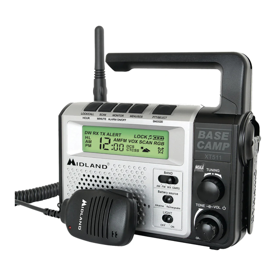
Midland XT511
1. REFERENCE TEST EQUIPMENT
• A. HP8921A Cell site test set or HP8920A, B Communication Test Set with
Spectrum
Analyzer option.
• B. Fluke 187 Digital Voltmeter
• C. HP E3615A Power supply
2. TEST POINT
A. ANTENNA
B. GMRS VCO reference voltage: Test point 1 is prepared.
C. RX audio output
D. TX Mic. Input
E. Battery Vcc
F. Call Key
G. Menu Key
H. Monitor Key
I. PTT Key
J. Scan key
Note. : All key can be activated when connect with ground.
3. VCO ALIGNMENT
A. Set unit to Channel 1 and connect a voltmeter to TP1 (VCO PD).
B. Press & hold PTT.
C. Extend L141 until the voltmeter reads 1.5V.
D. Put shield-can on VCO area and monitor the voltage on TP1. The voltage should be
1.5Vdc +/-0.2Vdc. If the voltage is not 1.5Vdc +/-0.2Vdc, realign L141 until meet to
requirement.
E. Release PTT button so units is in receiving mode and monitor the voltage on TP1. The
voltage should be in the range 1.5Vds +/-0.5V
F. Set unit to channel 14.
6. Press & hold the PTT switch and observe the voltage on TP1. The voltage should be 2 -
3,5 Vdc.
7. Release PTT and observe the voltage on TP1. The voltage should read between 2.0 - 3.5
Vdc.
Note : VCO shield-can should be soldered after VCO alignment is finished.
4. TRANSMITTER FREQUENCY ALIGNMENT
A. While Press & hold the PTT, Menu and Menu buttons, the knob clockwise to switch on
radio..
B. Align Up or Down button such that the output frequency is equal to the channel frequency
with a maximum error of +/- 200 Hz.
ALIGNMENT PROCEDURE
www.radioaficion.com
: Test point is not prepared. Use antenna contact with
ANTGND1(antenna ground).
: Speaker terminals & ear jack are prepared.
: Use ear-jack(3.5mm) with 10uF coupling capacitor.
: Test point is not prepared. Please use mechanical contact.
Plus terminal is posited on upper right corner of PCB (Battery
cover side view).
: Test point UP is prepared.
: Test point MENU is prepared.
: Test point MONITOR is prepared.
: Test point PTT is prepared.
: Test point SCAN is prepared.
the
Advertisement

Related Manuals for Midland XT511


Summary of Contents for Midland XT511
- Page 1 Midland XT511 ALIGNMENT PROCEDURE www.radioaficion.com 1. REFERENCE TEST EQUIPMENT • A. HP8921A Cell site test set or HP8920A, B Communication Test Set with Spectrum Analyzer option. • B. Fluke 187 Digital Voltmeter • C. HP E3615A Power supply 2. TEST POINT A.
-
Page 2: Alignment Procedure
XT511 ALIGNMENT PROCEDURE 5. TRANSMITTER OUTPUT POWER CONFIRMATION A. Set unit to channel 1. B. Press & hold the PTT button. C. Transmit power should normally be between 3.0W to 4.0W. (Conducted) D. Set unit to channel 14. E. Press & hold the PTT button. Ensure that Tx Power meets 0.2W - 0.8W. (conducted) 6. - Page 3 XT511 ALIGNMENT PROCEDURE FREQUENCIES TABLE Channel Freq. MHz Channel Freq. MHz 462.5625 467.6625 462.5875 467.6875 462.6125 467.7125 462.6375 462.5500 462.6625 462.5750 462.6875 462.6000 462.7125 462.6250 467.5625 462.6500 467.5875 462.6750 467.6125 462.7000 467.6375 462.7250...
- Page 4 XT511 CAMP RADIO LABORATORY TESTING PROCEDURES UNIT TEST - (UNIT ASSEMBLED) TEST PREPARATION 1) Install 4 “AA” alkaline batteries (observe polarity markings). - Left upper terminal is the system plus polarity - Right bottom terminal is the system minus polarity.
- Page 5 XT511 CAMP RADIO LABORATORY TESTING PROCEDURES SPECIFIC TEST METHODS AND GUIDANCE Modulation Characteristics - (paragraph 2.1047(a) of the Rules) FOR TX AUDIO FILTER RESPONSE Connect audio generator with 10uF coupling capacitor to microphone input jack. Press PTT button. Connect RF output with modulation meter. (Filters of modulation meter should be set to a 50Hz to 15KHz.)
-
Page 6: General Specification
XT511 PRODUCTION SPECIFICATION 1. GENERAL SPECIFICATION Items Specifications Tx Frequency range 462.550MHz 467.7125MHz Tx VCO Frequency range Same as item 1 RX Frequency range Same as item 1 RX VCO Frequency range 441.1500MHz 446.3125MHz ( Lower Heterodyne ) Channel Number... - Page 7 XT511 PRODUCTION SPECIFICATION 2. DETAILED SPECIFICATION A. RECEIVER SECTIONS * Normal test condition * TYP. LIMIT 1. MAXIMUM USABLE SENSITIVITY * 1KHz +/-1.5KHz DEV. -120dBm <-118dBm * REF. CHANNEL 1 & 8 2. 20dB QUIETING SENSITIVITY * 1HKz +/-1.5KHz DEV.
-
Page 8: Production Specification
XT511 PRODUCTION SPECIFICATION B. TRANSMITTER SECTIONS LIMIT 1. TRANSMITTER FREQUENCY TOL. * REF. CHANNEL 1 <+/-200Hz 2. TRANSMITTER RF POWER * REQUIRED CONDUCTIVE CONNECTION * REF. CHANNEL 1 Hi Power 3.5W 3.0 - 4.0 * At 6Vdc Low Power 0.6W 0.2 - 0.8...
Need help?
Do you have a question about the XT511 and is the answer not in the manual?
Questions and answers