Table of Contents
Advertisement
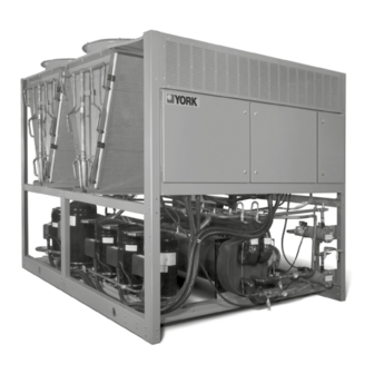
AIR-COOLED SCROLL CHILLER
Supersedes 150.72-NM3 (811)
Form 150.72-NM3 (1020)
INSTALLATION, OPERATION, MAINTENANCE
035-21911-001
YLAA0195 - YLAA0515
AIR-COOLED SCROLL CHILLERS
WITH MICROCHANNEL CONDENSER COILS
STYLE A (50 HZ)
57 - 142 TON
R-410A
Issue Date:
Products are produced at a
f a c i l i t y w h o s e q u a l i t y -
management systems are
October 5, 2020
ISO9001 certified.
Advertisement
Table of Contents
Troubleshooting


Need help?
Do you have a question about the YLAA0285SE and is the answer not in the manual?
Questions and answers