Table of Contents
Advertisement
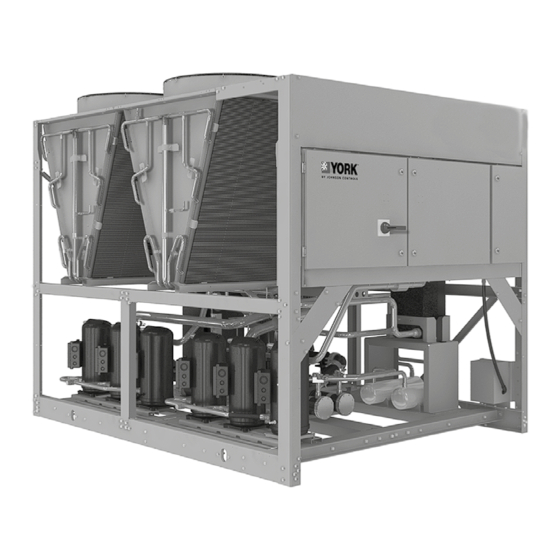
Air-Cooled Scroll Chiller
Supersedes: 150.72-ICOM6 (1023)
Form 150.72-ICOM6 (1223)
Installation, Operation, Maintenance
035-23572-100
YLAA0041 – YLAA0230
Air-Cooled Scroll Chillers
with Brazed Plate Heat Exchanger
Style B (60 Hz) 4 to 12 Fan
40 ton to 230 ton
140 kW to 800 kW
R-410A,
R-454B
Issue Date:
Products are produced at a
December 19, 2023
f a c i l i t y w h o s e q u a l i t y -
management systems are
ISO9001 certified.
Advertisement
Table of Contents
Troubleshooting

Related Manuals for York YLAA0100SE


Summarization of Contents
Section 1: General chiller information and safety
Introduction
Overview of YORK YLAA chillers, their design standards, and manual scope.
Warranty
Details Johnson Controls' warranty terms, limitations, and conditions for equipment.
Handling
Precautions for handling assembled units to avoid damage during transport.
Safety and quality
Standards and compliance for YLAA chillers, ensuring safety and quality.
Misuse of equipment
Guidelines on suitability for application, structural support, mechanical strength, and general access.
Pressure systems
Safety considerations when working with the unit's refrigerant vapor and liquid under pressure.
Electrical
Safety procedures for electrical work, including power isolation and qualified personnel.
Refrigerants and oils
Handling requirements for A2L refrigerants and safety precautions.
Safety labels
Explanation of safety symbols and warning labels used in the document.
Section 2: Product description
Introduction
Overview of YORK YLAA Air-Cooled Scroll Chillers and their applications.
General system description
Description of compressors, cooler (evaporator), and their specifications.
Brazed plate evaporator
Details on the compact, high-efficiency brazed plate heat exchanger (BPHE) construction.
Condenser
Information on condenser coils, microchannel condensers (MCHX), fans, motors, and control center.
Control center
Description of the microprocessor control system, display, and keypad functions.
Entry keys
Explanation of using Entry keys for setpoints, cutouts, and scheduling.
Unit keys
Functions of Unit keys for setting time and unit options.
Oper data key
Accessing unit and system operating parameters via the OPER DATA key.
Communications
Details on native BACnet and Modbus communication capabilities.
Building automation system interface
How the chiller interfaces with Building Automation Systems via analog inputs.
Power panel
Components of the power panel, including compressor and fan connections.
Accessories and options
Overview of available accessories and options for the chiller.
Condenser and cabinet options
Options for condenser protection against corrosive environments and enclosure panels.
Sound attenuation
Options for reducing chiller noise levels, including acoustic sound blankets and quiet fans.
Vibration isolators
Details on spring type or neoprene pad isolators for mounting the unit base rails.
Section 3: Handling and storage
Rigging and lifting label
Warning label on chiller packaging regarding proper rigging and lifting procedures.
Delivery and storage
Precautions for unit delivery, storage, and handling to ensure quality and reliability.
Inspection
Procedure for inspecting the unit upon delivery to ensure all components are present and undamaged.
Moving the chiller
Guidelines for safely moving the chiller, emphasizing lifting by the base frame.
Lifting weights
Information on determining unit shipping weight and configuration-dependent weights.
Lifting using lugs
Instructions for using lifting lugs, including correct insertion and attachment methods.
Lifting using shackles
Procedure for inserting shackles into base frame holes and securing them.
Section 4: Installation
Installation checklist
Steps to complete before placing units into operation, covering inspection, piping, and wiring.
Location and clearances
Guidelines for selecting chiller location and ensuring adequate clearances for airflow and servicing.
Foundation
Requirements for mounting the unit on a flat, level foundation capable of supporting its weight.
Rooftop locations
Considerations for rooftop installations, including structural strength and roof protection.
Noise sensitive locations
Recommendations for siting chillers away from noise-sensitive areas.
Chilled liquid piping
Instructions for connecting the unit water piping, ensuring cleanliness and proper flow.
Pipework arrangement
Suggested pipework arrangements for single and multiple unit installations.
Fan discharge ducting
Recommendations for ductwork to ensure satisfactory unit operation and prevent warranty invalidation.
Wiring
Guidance on field wiring for power and controls, emphasizing NEC compliance.
Relief valves
Information on high and low pressure relief valve settings.
High pressure cutout
Details on the high pressure cutout settings for each system.
Evaporator pump start contacts
Conditions under which evaporator pump dry contacts are energized.
System run contacts
Information on normally-open auxiliary contacts for monitoring system status.
Alarm status contacts
Details on normally-open alarm contacts that close when the system functions normally.
Remote start/stop contacts
Wiring instructions for remotely starting and stopping the chiller.
Load limit input
Explanation of the load limiting feature and its conjunction with PWM inputs.
Single-point supply connection – terminal block, non-fused disconnect switch or circuit breaker
Diagrams for single-point power connections including disconnects and circuit breakers.
User control wiring inputs
Diagrams illustrating user control wiring inputs and their terminal connections.
Specification of water
Guidelines for water quality to prevent BPHE clogging and maintain system integrity.
Thermal dispersion flow switch
Operating principle, service information, and wiring for the thermal dispersion flow switch.
User control wiring outputs
Diagrams showing user control wiring outputs and their terminal connections.
Section 5: Technical data
Operational limitations
Guidelines on operating temperatures, flows, and site conditions for optimal performance.
Physical data YLAA0041 to YLAA0230, 60 Hz
Detailed physical and nominal data for standard efficiency YLAA units.
Electrical data
Micropanel power supply, voltage limitations, and compressor heater specifications.
Voltage limitations
Absolute voltage limits for operation to prevent compressor damage.
Compressor heaters
Information on standard compressor heaters and their operation timing.
Pump Electrical Data 60 Hz
Electrical data for various pump models including FLA and LRA.
Transformer Load
VA ratings for transformer loads based on voltage.
Electrical data without pumps, R-410A
Electrical specifications for YLAA units with R-410A refrigerant.
Electrical data without pumps, R-454B
Electrical specifications for YLAA units with R-454B refrigerant.
Wiring lugs
Table detailing wiring lug specifications for various chiller models and voltages.
Electrical notes
Important notes regarding electrical connections, MCA, fuse sizes, and grounding.
Wiring diagrams
Schematic diagrams illustrating elementary wiring for the unit.
Section 6: Commissioning
Authorized Commissioning Personnel
Requirement for authorized Johnson Controls personnel for unit commissioning.
Preparation, with power off
Basic checks to perform with the unit power switched OFF before commissioning.
Refrigerant charge
Safety and handling procedures for A2L refrigerants during charging.
Charging refrigerant
Step-by-step instructions for charging refrigerant into the system after vacuuming.
Compressor heaters
Verification of compressor heater operation based on ambient temperature.
Compressor oil
Procedure for adding oil to compressor systems and checking oil levels.
Switch settings
Ensuring correct chiller OFF/ON switch and panel settings.
Water system
Verification of chilled liquid system installation, water flow, and pressure drops.
Commissioning the pump VFD
Steps to program the Variable Speed Drive (VSD) for the pump.
Programming the drive
Instructions to access Service Mode and program drive parameters.
Parameter structure
Overview of the drive's parameter structure, including Short and Long Parameter Modes.
Drive programming parameters
Table of drive parameters with their settings, limits, and defaults.
Setting the adjustable breaker
Procedure for setting the over-current protection (MOCP) on adjustable breakers.
Determining proper oil levels
Charts listing proper oil levels for tandem and trio compressor manifold sets.
INSTALLATION CHECKLIST
Comprehensive checklist for unit installation and pre-startup procedures.
START-UP CHECKLIST
Detailed checklist for unit startup procedures, including panel checks and compressor tests.
Unit Checks (No Power)
Pre-startup checks of the unit with power off, including inspection and piping.
COMPRESSOR HEATER
Procedure for checking compressor heater power supply.
Panel checks (Power On - Both Unit Switch Off )
Checks to perform on panel components after applying power.
SETPOINTS ENTRY LIST
Reference list for unit options, cooling setpoints, and program setpoints.
CHECKING SUPERHEAT AND SUBCOOLING
Procedures for calculating and setting suction superheat and subcooling.
LEAK CHECKING
Instructions for performing leak checks on compressors, fittings, and piping.
Section 7: Unit controls
Introduction
Overview of the YORK Control Center, a microprocessor-based system for liquid chiller control.
IPU II and I/O boards
Description of the IPU II and I/O boards functioning as a single microprocessor controller.
Keypad
Functionality of the 12-button keypad for accessing system parameters and setpoints.
Unit switch
Description of the unit ON/OFF switch located beneath the keypad.
Battery backup
Explanation of the Real Time Clock and its internal battery backup for retaining data.
Programming the number of compressors
How to program the total number of compressors for dual system chillers.
Status key
Using the STATUS key to determine current chiller operating status and messages.
General status messages
Explanation of general status messages displayed for SYS 1 and SYS 2.
DAILY SCHEDULE SHUTDOWN
Indicates the unit is shut down due to a programmed daily or holiday schedule.
REMOTE STOP NO RUN PERM
Shows a remote start/stop contact is open, preventing unit operation.
FLOW SWITCH OPEN
Indicates the flow switch contacts are open, preventing unit operation.
SYS SWITCH OFF
Indicates a system switch under OPTIONS is turned OFF.
Unit Safeties
Explanation of unit safeties that cause compressor shutdown and auto reset.
Fault and inhibit codes and reset
Table of fault and inhibit codes and their reset procedures.
Status Key Messages Quick Reference List
A quick reference list of status and fault messages displayed on the unit.
Display/print keys
Functions of the Display/Print keys for retrieving system and unit information.
Oper data key
Accessing unit and system operating parameters via the OPER DATA key.
COOLING DEMAND
Indicates the current step in the capacity control scheme.
LEAD SYSTEM IS SYSTEM NUMBER 2
Shows which system is currently acting as the LEAD system.
EVAPORATOR HEATER STATUS IS XXX
Displays the status of the evaporator heater.
EVAPORATOR WATER PUMP STATUS XXXX
Indicates the status of the evaporator water pump.
Entry keys
Using Entry keys to view and change programmed values.
Setpoints keys
Programming cooling setpoints, daily schedule, and safeties using the SETPOINTS keys.
Cooling Setpoints
Programming the Cooling Setpoint and Range for leaving/return chilled liquid.
Leaving chilled liquid control
Control logic for maintaining leaving chilled liquid temperature within a set range.
Return chilled liquid control
Control logic for maintaining return chilled liquid temperature within a set range.
Schedule/advance day key
Programming the seven-day daily and holiday schedules for unit operation.
Cooling Setpoint, Programmable Limits, and Defaults
Table of cooling setpoint limits and default values for water and glycol cooling.
Program key
Accessing and changing programmable operating parameters via the PROGRAM key.
System trip volts
Programming high current trip settings for individual systems and the total chiller.
Unit Trip Volts
Programming high current trip settings for the total chiller.
Program key limits and default
Table of programmable limits and default values for various program settings.
Setpoints Quick Reference List
Quick reference list for programmable setpoints including VSD fan and cooling parameters.
Service mode
Entering Service Mode to view/modify inputs, outputs, and configuration parameters.
Selecting low temperature
Steps to enable LOW TEMPERATURE operation for glycol cooling.
Unit keys
Overview of programmable options accessible via the OPTIONS key.
Options key
Using the OPTIONS key to scroll and change programmable options.
Option 1: Language
Selecting the display language for the chiller control panel.
Option 2 : System switches (two system units only)
Controlling system operation (ON/OFF) via system switches.
Option 3: Ambient control type
Setting the ambient control type to standard or low ambient.
Option 4: Local/remote control type
Selecting the control mode for monitoring or controlling the chiller remotely.
Option 5: Unit control mode
Setting the unit control mode to Return or Leaving chilled liquid.
Option 6: Display units
Choosing between Imperial (°F/PSIG) and SI (°C/barg) units for display.
Option 7: Lead/lag type (two system units only)
Selecting lead/lag control between systems for average compressor run hour equalization.
Option 8: Condenser fan control mode
Setting condenser fan control based on discharge pressure or ambient/discharge pressure.
Option 9: Manual override mode
Enabling or disabling manual override of the daily schedule.
Option 11: Power fail restart
Configuring automatic or manual restart after a power failure.
Option 12: Soft start enable/disable
Enabling or disabling the soft start feature for compressors.
Option 13: Unit type
Setting the unit type to Liquid Chiller, ensuring correct operation.
Option 14: Refrigerant type
Selecting the refrigerant type (R-410A) under Service Mode.
Option 15: Expansion valve type
Selecting the expansion valve type, typically thermostatic for YLAA.
Option 16: Flash card update
Information on using a Flash Card for operating program updates.
Option 17: Remote temperature reset
Configuring remote temperature reset input using voltage or current signals.
Option 18: Pump control
Controlling onboard or external pumps via dry contacts or specific options.
Option 19: Pump selection
Selecting pump options, specifically for dual pump configurations.
Option 20: Hot gas bypass type
Displaying the programmed hot gas bypass type for R-410A units.
Option 21: Flash card data logging
Enabling or disabling data logging to an SD card.
Option 22: Temperature sensors enable
Enabling or disabling discharge and YCWL temperature sensors.
Option 23: Variable water outlet mode
Enabling or disabling the variable water outlet mode.
Clock
Viewing and setting the current day, time, and date for accurate operation.
Unit Keys Options Programming Quick Reference List
A quick reference list for unit key setpoints and option programming.
BACnet, Modbus, N2, and YorkTalk 2 communications
Using serial communication for chiller parameter access and control.
Minimum, Maximum and Default Values
Table of minimum, maximum, and default values for communication parameters.
Values Required for BAS Communication
Setup requirements for BACnet, Modbus RTU, and YorkTalk 2 communication protocols.
BACnet and Modbus communications
Reading and modifying chiller data via BACnet or Modbus network connections.
Communications data map notes
Notes regarding communication data maps and BACnet object types.
YorkTalk 2 communications
Receiving and transmitting data via E-Link Gateway for YorkTalk 2.
Section 8: Unit operation
Unit operating sequence
Description of the chiller's operating sequence upon power application and compressor staging.
Capacity control
How the control system evaluates cooling needs and regulates temperature.
Suction pressure limit controls
Anticipatory controls to prevent low-pressure cutouts and manage loading.
Discharge pressure limit controls
Microprocessor actions to unload systems before safety limits are reached.
Leaving chilled liquid control
Control logic for maintaining leaving chilled liquid temperature within setpoint and range.
Leaving chilled liquid control override to reduce cycling
Temporary setpoint adjustment to avoid compressor cycling and reduce short cycling.
Leaving chilled liquid system lead/lag and compressor sequencing
Using Lead/Lag option to equalize run hours and sequence compressors.
Return chilled liquid system lead/lag and compressor sequencing
Lead/Lag options for equalizing run hours and sequencing compressors.
Anti-recycle timer
Programmable timer to ensure systems do not short cycle.
Anti-Coincidence Timer
Software timer to prevent simultaneous compressor starts between systems.
Evaporator pump control and YORK hydro kit pump control
Control logic for evaporator pump operation based on various conditions.
Evaporator heater control
Evaporator heater control based on ambient air temperature.
Pumpdown control
System pump-down feature upon shutdown.
Standard condenser fan control
Condenser fan control based on discharge pressure, with programmable setpoints.
VSD fan
Control of VSD fans for extended minimum starting ambient temperature.
Changing the switch point of the thermal dispersion flow switch
Steps to change the factory-set LED 7 for the thermal dispersion flow switch.
Load limiting
Feature to prevent unit loading beyond preferred value based on compressor count.
Compressor run status
Indication of compressor run status via closure of contacts.
Alarm status
System or unit shutdown indication via normally-open alarm contacts.
Remote BAS/EMS temperature reset using a voltage or current signal
Resetting chilled liquid setpoint using remote analog inputs.
Section 9: Service and troubleshooting
Clearing history buffers
Procedure for clearing the unit's history buffers using the HISTORY key.
Resetting system lockout faults
Manual reset procedure for systems locked out due to multiple faults.
Service mode
Entering Service Mode to view and modify unit outputs, configuration, and inputs.
Service mode, outputs
Viewing and modifying unit outputs (except compressors) in Service Mode.
Service mode, chiller configuration
Modifying chiller configuration parameters like refrigerant type and expansion valve type.
Service mode, analog and digital inputs
Viewing analog and digital inputs to the microboard in Service Mode.
Control inputs/outputs
Reference list for microboard connection points for digital and analog I/O.
Microboard Layout
Diagram illustrating the layout of the microboard and its connectors.
Checking inputs and outputs
Procedures for checking digital and analog inputs and outputs on the unit.
Analog inputs, pressure
Connecting and interpreting analog inputs for pressure transducers.
Table 33: Pressure Transducers
Correlation table for pressure transducer voltage readings to pressure values.
Digital outputs
Information on digital outputs located on TB7, TB8, TB9, and TB10 of the microboard.
I/O Board Relay Contact Architecture
Diagram illustrating the relay contact architecture on the I/O board.
Data logging to flash
Enabling and understanding the content of data logging to an SD card.
Optional printer installation
Required parts and procedures for optional printer installation.
Troubleshooting
Common problems, causes, and solutions for unit operation issues.
Section 10: Maintenance
Compressors
Procedures for checking compressor oil levels and performing oil analysis.
Microchannel coil cleaning
Essential procedures for maintaining microchannel heat exchanger integrity and heat transfer.
Cleaning procedure required for standard and environment guard microchannel coils
Detailed steps for cleaning standard and environment guard microchannel coils.
Cleaning procedure for environment guard premium microchannel coils
Steps for cleaning premium microchannel coils, including salt reducer application.
Steps to touch-up small sections of finned coil surface on microchannel coils
Procedure for touching up small sections of finned coil surfaces with paint.
Operating parameters
Regular checks on system operating temperatures and pressures within limitations.
On-board battery backup
Information on the Real Time Clock chip and its battery backup function.
Thermal dispersion flow switch
Checking the sensor tip for buildup to ensure accurate sensitivity.
Brazed plate heat exchanger (evaporator) heater
Safety warning regarding disconnecting 120 VAC power to the evaporator heater.
Overall unit inspection
Performing periodic inspections for proper equipment operation and identifying issues.
Temperature conversion chart
Charts for converting between Fahrenheit and Celsius temperatures.
R-410A pressure temperature chart
Pressure-temperature correlation chart for R-410A refrigerant.
R-454B pressure temperature chart
Pressure-temperature correlation chart for R-454B refrigerant.
SI-metric conversion
Factors for converting English units to common SI Metric values.
Need help?
Do you have a question about the YLAA0100SE and is the answer not in the manual?
Questions and answers