Table of Contents
Advertisement
Quick Links
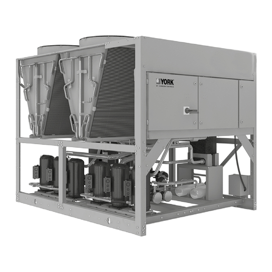
Air-Cooled Scroll Chiller
with Bitzer Compressor
Installation, Operation,
Supersedes: 150.72-ICOM8.EN.GB (817)
Form 150.72-ICOM8.EN.GB (924)
Maintenance
YLAA0195 – YLAA0517
Air-Cooled Scroll Chillers with
Brazed Plate Heat Exchanger
Style B (50 Hz) 4 fan to 8 fan
55 Ton to 150 Ton
196 kW to 520 kW
R-410A
Issue Date:
September 20, 2024
Advertisement
Table of Contents
Troubleshooting

Related Manuals for York YLAA0195


Summary of Contents for York YLAA0195
- Page 1 Bitzer Compressor Installation, Operation, Supersedes: 150.72-ICOM8.EN.GB (817) Form 150.72-ICOM8.EN.GB (924) Maintenance YLAA0195 – YLAA0517 Air-Cooled Scroll Chillers with Brazed Plate Heat Exchanger Style B (50 Hz) 4 fan to 8 fan 55 Ton to 150 Ton 196 kW to 520 kW...
-
Page 2: Read Before Proceeding
FORM 150.72-ICOM8.EN.GB ISSUE DATE 9/20/2024 IMPORTANT! READ BEFORE PROCEEDING! GENERAL SAFETY GUIDELINES This equipment is a relatively complicated apparatus. which it is situated, as well as severe personal injury or During rigging, installation, operation, maintenance, death to themselves and people at the site. or service, individuals may be exposed to certain com- This document is intended for use by owner-authorized ponents or conditions including, but not limited to:... -
Page 3: Changeability Of This Document
FORM 150.72-ICOM8.EN.GB ISSUE DATE 9/20/2024 Changeability of this document In complying with the Johnson Controls® policy for It is the responsibility of rigging, lifting, and operating/ continuous product improvement, the information con- service personnel to verify the applicability of these tained in this document is subject to change without documents to the equipment. - Page 4 YLAA 0390 DEVELOPMENT LEVEL DESIGN REFRIGERANT UNIT TYPE E = R-410A SERIES YORK Scroll Air DESIGNATOR Cooled S = Standard Efficiency STARTER Y = High Efficiency (Round Tube) X = Across the Line Starter CAPACITY T = Soft Start 0195...
-
Page 5: Table Of Contents
FORM 150.72-ICOM8.EN.GB ISSUE DATE 9/20/2024 Table of Contents SECTION 1 – GENERAL CHILLER INFORMATION AND SAFETY ..............11 Introduction ..............................11 Warranty ................................. 11 Handling ................................. 11 Safety And Quality ............................11 About This Manual............................12 Misuse Of Equipment ............................. 12 SECTION 2 –... - Page 6 FORM 150.72-ICOM8.EN.GB ISSUE DATE 9/20/2024 Table of Contents (Continued) SECTION 5 – TECHNICAL DATA ........................35 Operational Limitations ........................... 35 Physical Data si .............................. 37 Electrical Data ..............................39 Compressor Heaters ............................39 Electrical Notes .............................. 44 Dimensions ..............................58 Dimensions ..............................59 Weight Distribution And Isolator Mounting Positions ..................
- Page 7 Return Chilled Liquid System Lead/Lag And Compressor Sequencing ............123 Anti-Recycle Timer ............................123 Anti-Coincidence Timer ..........................123 Evaporator Pump Control And York Hydro Kit Pump Control ............... 124 Evaporator Heater Control ........................... 124 Pumpdown Control ............................124 Standard Condenser Fan Control ........................ 124 Load Limiting ..............................
- Page 8 FIGURE 10 - Control Wiring Outputs ........................33 FIGURE 11 - Elementary Wiring Diagram ......................48 FIGURE 12 - Fan Wiring, Standard Low Sound or Ultra Quiet, YLAA0195 - YLAA0517 ........50 FIGURE 13 - Fan Wiring, Standard Low Sound or Ultra Quiet, YLAA0195 - YLAA0517 ........52 FIGURE 14 - Power Options Connection Diagram ....................54...
- Page 9 FORM 150.72-ICOM8.EN.GB ISSUE DATE 9/20/2024 List of Tables TABLE 1 - Temperatures and Flows ........................35 TABLE 2 - Physical Data (Metric) ...........................37 TABLE 3 - Micropanel Power Supply ........................39 TABLE 4 - Voltage Range ............................39 TABLE 5 - Electrical Data Without Pumps ......................40 TABLE 6 - Transformer Load ..........................40 TABLE 7 - Cable Size .............................42 TABLE 8 - Cooling Setpoint, Programmable Limits and Defaults ................96...
- Page 10 FORM 150.72-ICOM8.EN.GB ISSUE DATE 9/20/2024 THIS PAGE INTENTIONALLY LEFT BLANK JOHNSON CONTROLS...
-
Page 11: Section 1 - General Chiller Information And Safety
ISSUE DATE 9/20/2024 SECTION 1 – GENERAL CHILLER INFORMATION AND SAFETY INTRODUCTION YORK YLAA chillers are manufactured to the highest All warranty claims must specify the unit model, serial design and construction standards to ensure high per- number, order number and run hours/starts. Model and... -
Page 12: About This Manual
FORM 150.72-ICOM8.EN.GB SECTION 1 – GENERAL CHILLER INFORMATION AND SAFETY ISSUE DATE 9/20/2024 • GB25131 - Safety requirements of Positive dis- MISUSE OF EQUIPMENT placement and Centrifugal Water-chilling Pack- Suitability for Application ages. The unit is intended for cooling water or glycol solu- Responsibility for Safety tions and is not suitable for purposes other than those specified in these instructions. -
Page 13: Rotating Parts
FORM 150.72-ICOM8.EN.GB SECTION 1 – GENERAL CHILLER INFORMATION AND SAFETY ISSUE DATE 9/20/2024 Electrical Refrigerants and Oils The unit must be grounded. No installation or main- Refrigerants and oils used in the unit are generally non- tenance work should be attempted on the electrical toxic, non-flammable and non-corrosive, and pose no equipment without first switching power OFF, isolat- special safety hazards. -
Page 14: Figure 1 - Emergency Shutdown Handle
FORM 150.72-ICOM8.EN.GB SECTION 1 – GENERAL CHILLER INFORMATION AND SAFETY ISSUE DATE 9/20/2024 Emergency Shutdown (For circuit breaker or Safety Labels disconnect switch only) For safe operation, read the instructions In case of emergency, the control panel is fitted with an first. -
Page 15: Introduction
ISSUE DATE 9/20/2024 SECTION 2 – PRODUCT DESCRIPTION GENERAL SYSTEM DESCRIPTION INTRODUCTION YORK YLAA Air-Cooled Scroll Chillers provide Compressors chilled water for all air conditioning applications us- The chiller has suction-gas cooled, hermetic, scroll ing central station air handling or terminal units. They compressors. - Page 16 FORM 150.72-ICOM8.EN.GB SECTION 2 – PRODUCT DESCRIPTION ISSUE DATE 9/20/2024 The evaporator is equipped with a thermostat-con- • System pressures (each circuit) trolled heater. The heater provides freeze protection • Operating hours and starts (each compressor) for the evaporator down to -29°C (-20°F) ambient. •...
-
Page 17: Communications
FORM 150.72-ICOM8.EN.GB SECTION 2 – PRODUCT DESCRIPTION ISSUE DATE 9/20/2024 • Discharge pressure (optional) BUILDING AUTOMATION SYSTEM INTERFACE • Liquid Temperature Reset via a Johnson Controls ISN DDC or Building Automation System (by The Microprocessor Board can accept a 4 to 20 mil- others) via a 4 to 20 milliamp or 0 to10VDC input liamp, or 0 to 10VDC input to reset the leaving chiller •... -
Page 18: Control Transformer
FORM 150.72-ICOM8.EN.GB SECTION 2 – PRODUCT DESCRIPTION ISSUE DATE 9/20/2024 Single-Point Non-Fused Disconnect Switch Service Suction Isolation Valve Service suction (ball-type) isolation valves are added Unit-mounted disconnect switch with external, lockable to unit per system (discharge service ball-type isolation handle (in compliance with Article GB), can be supplied valve is standard on each circuit). - Page 19 FORM 150.72-ICOM8.EN.GB SECTION 2 – PRODUCT DESCRIPTION ISSUE DATE 9/20/2024 Condenser and Cabinet Options MCHX End Hail Guard Louvered panel attached to exposed MCHX end. (Fac- MCHX Condenser protection against corrosive envi- tory-Mounted) ronments is available by choosing any of the following options.
-
Page 20: Figure 2 - Unit Components (Front)
FORM 150.72-ICOM8.EN.GB SECTION 2 – PRODUCT DESCRIPTION ISSUE DATE 9/20/2024 POWER POWER PANEL PANEL ITEM DESCRIPTION Fan Assemblies MCHX Condenser Control Panel Compressors Receiver Included with Optional Heat Recovery Condenser Filter Driers FIGURE 2 - UNIT COMPONENTS (FRONT) JOHNSON CONTROLS... -
Page 21: Figure 3 - Unit Components (Side)
FORM 150.72-ICOM8.EN.GB SECTION 2 – PRODUCT DESCRIPTION ISSUE DATE 9/20/2024 ITEM DESCRIPTION Fan Deck MCHX Condenser Coil Headers Control and Power Panels Compressors Brazed Plate Evaporator Formed Steel Base Rails Hydro-Kit Pumps And Motors (Optional) FIGURE 3 - UNIT COMPONENTS (SIDE) JOHNSON CONTROLS... -
Page 22: Figure 4 - Power Panel Components
FORM 150.72-ICOM8.EN.GB SECTION 2 – PRODUCT DESCRIPTION ISSUE DATE 9/20/2024 LD19857 ITEM DESCRIPTION Fan Contactor Fan Circuit Breaker Compressor Circuit Breaker XTBF1 Control Relay Compressor Contactors FIGURE 4 - POWER PANEL COMPONENTS JOHNSON CONTROLS... -
Page 23: Figure 5 - Power Panel / Control Components
FORM 150.72-ICOM8.EN.GB SECTION 2 – PRODUCT DESCRIPTION ISSUE DATE 9/20/2024 LD19858, LD19859 ITEM DESCRIPTION Compressor Circuit Breakers Fan Circuit Breakers Fan Contactors Phase Sequence Module Microcomputer Control Center Display Keypad Compressor COntactors Control Relay XTBF2 XTBC2 Transformer Microboard (IPUII and I/O Boards) XTBC1 FIGURE 5 - POWER PANEL / CONTROL COMPONENTS JOHNSON CONTROLS... -
Page 24: Figure 6 - Process And Instrumentation Diagram
FORM 150.72-ICOM8.EN.GB SECTION 2 – PRODUCT DESCRIPTION ISSUE DATE 9/20/2024 Control Functions: DV - Display Value Fans Fans Components: CHT - Chilled Liquid Temperature HPC - High Pressure Cutout Pressure Relief Valve LPC - Low Pressure Cutout HPL - High Pressure Load Limiting Service (Ball) Valve LTC - Low Temperature Cutout Expansion Valve... -
Page 25: Section 3 - Handling And Storage
FORM 150.72-ICOM8.EN.GB ISSUE DATE 9/20/2024 SECTION 3 – HANDLING AND STORAGE LD19197 Rigging and lifting should only be done by a professional rigger in accordance with a written rig- ging and lifting plan. The most appropriate rigging and lifting method will depend on job specific factors, such as the rigging equipment available and site needs. -
Page 26: Moving The Chiller
FORM 150.72-ICOM8.EN.GB SECTION 3 – HANDLING AND STORAGE ISSUE DATE 9/20/2024 MOVING THE CHILLER LIFTING USING LUGS Prior to moving the unit, ensure that the installation Units are provided with lifting holes in the base frame site is suitable for installing the unit and is easily ca- which accept the accessory lifting lug set as shown in pable of supporting the weight of the unit and all as- the figure below. -
Page 27: Section 4 - Installation
FORM 150.72-ICOM8.EN.GB ISSUE DATE 9/20/2024 SECTION 4 – INSTALLATION To ensure warranty coverage, this equip- In installations where winter operation is intended and ment must be commissioned and serviced snow accumulations are expected, additional height by an authorized Johnson Controls must be provided to ensure normal condenser air flow. -
Page 28: Spring Isolators (Optional)
FORM 150.72-ICOM8.EN.GB SECTION 4 – INSTALLATION ISSUE DATE 9/20/2024 The piping to and from the cooler must be designed to SPRING ISOLATORS (OPTIONAL) suit the individual installation. It is important that the When ordered, isolators will be furnished. Identify the following considerations be observed: isolator, locate at the proper mounting point, and adjust per instructions. -
Page 29: Pipework Arrangement
FORM 150.72-ICOM8.EN.GB SECTION 4 – INSTALLATION ISSUE DATE 9/20/2024 When ducting is to be fitted to the fan discharge it is PIPEWORK ARRANGEMENT recommended that the duct should be the same cross- The following are suggested pipework arrangements sectional area as the fan outlet and straight for at least for single unit installations, for multiple unit installa- three feet (1 meter) to obtain static regain from the fan. -
Page 30: Relief Valves
FORM 150.72-ICOM8.EN.GB SECTION 4 – INSTALLATION ISSUE DATE 9/20/2024 aluminum to copper. This transition should be done in Alarm Status Contacts an external box separate to the power panel. Copper Normally-open contacts are available for each re- conductors can then be run from the box to the chiller. frigerant system. -
Page 31: Single-Point Supply Connection - Terminal Block, Non-Fused
FORM 150.72-ICOM8.EN.GB SECTION 4 – INSTALLATION ISSUE DATE 9/20/2024 SINGLE-POINT SUPPLY CONNECTION – TERMINAL BLOCK, NON-FUSED DISCONNECT SWITCH OR CIRCUIT BREAKER Power Panel Power Panel Power Panel Control Panel Control Panel Control Panel XTBC1 Terminal Block, Terminal Block, MICROPANEL MICROPANEL NF Disconnect SW NF Disconnect SW or Circuit Breaker... -
Page 32: Flow Switch
FORM 150.72-ICOM8.EN.GB SECTION 4 – INSTALLATION ISSUE DATE 9/20/2024 USER CONTROL WIRING INPUTS INTERNAL WIRING TO OPTIONAL REMOTE TEMP. RESET BOARD FLOW SWITCH ELECTRONIC FLOW SWITCH REMOTE UNLOAD STEP 1 PWM REMOTE TEMP RESET REMOTE START / STOP XTBC1 LD13130 All externally supplied contacts must be The unit evaporator heater uses 220VAC. -
Page 33: Figure 10 - Control Wiring Outputs
FORM 150.72-ICOM8.EN.GB SECTION 4 – INSTALLATION ISSUE DATE 9/20/2024 USER CONTROL WIRING OUTPUTS 2-XTBF INTERNAL WIRING TO EVAPORATOR HEATER INTERNAL WIRING TO HOT GAS SOLENOID VALVE 1-XTBF SYSTEM 2 ALARM DRY CONTACTS (OPEN = ALARM) SYSTEM 1 ALARM DRY CONTACTS (OPEN = ALARM) SYSTEM 2 RUN DRY CONTACTS (CLOSE = RUN) XTBC2 SYSTEM 1 RUN DRY CONTACTS (CLOSE = RUN) - Page 34 FORM 150.72-ICOM8.EN.GB ISSUE DATE 9/20/2024 THIS PAGE INTENTIONALLY LEFT BLANK JOHNSON CONTROLS...
-
Page 35: Section 5 - Technical Data
FORM 150.72-ICOM8.EN.GB ISSUE DATE 9/20/2024 SECTION 5 – TECHNICAL DATA OPERATIONAL LIMITATIONS TABLE 1 - TEMPERATURES AND FLOWS TEMPERATURE (°C) WATER FLOW (I/S) AIR ON CONDENSER (°C) MODEL HIGH EFFICIENCY YLAA0195HE 12.8 22.4 -17.8 51.7 YLAA0221HE 12.8 22.4 -17.8 51.7 YLAA0261HE 12.8 24.3... - Page 36 FORM 150.72-ICOM8.EN.GB SECTION 5 – TECHNICAL DATA ISSUE DATE 9/20/2024 HEAT EXCHANGER FLOW, GPM YLAA Evaporator Pressure Drop (Metric Units) Water Flow Rate (m EVAPORATOR YLAA MODELS 195HE, 221HE 261HE, 301HE 350HE, 457HE 391HE, 442HE 517HE JOHNSON CONTROLS...
-
Page 37: Table 2 - Physical Data (Metric)
FORM 150.72-ICOM8.EN.GB SECTION 5 – TECHNICAL DATA ISSUE DATE 9/20/2024 PHYSICAL DATA SI TABLE 2 - PHYSICAL DATA (METRIC) YLAA REFRIGERANT R-410A HIGH EFFICIENCY UNITS GENERAL UNIT DATA 0195HE 0221HE 0261HE 0301HE 0350HE 0391HE 0442HE 0457HE 0517HE Nominal Cooling Capacity Kw 344.6 380.5 427.3... - Page 38 FORM 150.72-ICOM8.EN.GB ISSUE DATE 9/20/2024 THIS PAGE INTENTIONALLY LEFT BLANK JOHNSON CONTROLS...
-
Page 39: Electrical Data
FORM 150.72-ICOM8.EN.GB SECTION 5 – TECHNICAL DATA ISSUE DATE 9/20/2024 ELECTRICAL DATA TABLE 3 - MICROPANEL POWER SUPPLY OVER CURRENT PROTECTION, CONTROL UNIT VOLTAGE POWER SEE NOTE B NF DISC SW NOTE A UNIT MODELS W/O VOLTAGE 220-1-60/50 CONTROL 30 A / 240V TRANS 200-1-60 30 A / 240V... -
Page 40: Table 5 - Electrical Data Without Pumps
MIN N/F MIN ELEM VOLT ELEM FUSE MODEL INCLUDE DISC SW FUSE & MIN CB MAX CB XFR AMPS) YLAA0195 YLAA0221 YLAA0261 YLAA0301 YLAA0350 YLAA0391 YLAA0442 YLAA0457 YLAA0517 NOTE: • Use this table along with Pump Electrical Data to determine electrical data of the unit plus the pump. - Page 41 FORM 150.72-ICOM8.EN.GB SECTION 5 – TECHNICAL DATA ISSUE DATE 9/20/2024 SYSTEM # 1 SYSTEM # 2 COMPR 1 COMPR 2 COMPR 3 STD FLOW FANS COMPR 1 COMPR 2 COMPR 3 STD FLOW FANS RLA LRA RLA LRA RLA LRA QTY FLA LRA RLA LRA RLA LRA RLA LRA QTY FLA LRA 26.9 26.9 26.9...
-
Page 42: Table 7 - Cable Size
FORM 150.72-ICOM8.EN.GB SECTION 5 – TECHNICAL DATA ISSUE DATE 9/20/2024 TABLE 7 - CABLE SIZE R/S/T GROUNDING CABLE MODEL VOLT CABLE SIZE CABLE SIZE QUANTITY YLAA QUANTITY PER PHASE 0195HE 0221HE 0261HE 0301HE 0350HE 0391HE 0442HE 0457HE 0517HE JOHNSON CONTROLS... -
Page 43: Electrical Notes
FORM 150.72-ICOM8.EN.GB SECTION 5 – TECHNICAL DATA ISSUE DATE 9/20/2024 ELECTRICAL NOTES NOTES circuit breakers must be used. Maximum HACR 1. Minimum Circuit Ampacity (MCA) is based on circuit breaker rating is based on 225% of the rat- 125% of the rated load amps for the largest mo- ed load amps for the largest motor plus 100% of tor plus 100% of the rated load amps for all other the rated load amps for all other loads included in... -
Page 44: Electrical Notes
- ZCPR COMPRESSOR CONTROL RELAY NOTE WELL {SEE NOTE} FAN CONTACTOR LINE - KF (INCLUDING COIL SUPPRESSOR) STANDARD YORK ACCESSORIES ARE - KH HEATER RELAY STANDARD YORK ACCESSORIES COMPRESSOR CONTACTOR (INCLUD- WIRING AND ITEMS SHOWN THUS ARE - KM ING COIL SUPPRESSOR) - Page 45 No controls {relays etc.} Should be mounted in any section of the control panel. Additionally, control wiring not con- nected to the YORK control panel should not be run through the panel. If these precautions are not followed, electrical noise could cause malfunctions or damage to the unit and its controls.
- Page 46 FORM 150.72-ICOM8.EN.GB SECTION 5 – TECHNICAL DATA ISSUE DATE 9/20/2024 ELECTRICAL NOTES AND LEGEND (CONT’D) Only fitted on low ambient units with thermal expanstion valves. 1-ETXVH fitted on 391, 442, 457, 517. 2-ETXVH fit- ted on 442, 457, 517. Not fitted on units with plate evaporators that have 7 or more fans. Only fitted on units with a plate heat exchanger evaporator.
- Page 47 FORM 150.72-ICOM8.EN.GB ISSUE DATE 9/20/2024 THIS PAGE INTENTIONALLY LEFT BLANK JOHNSON CONTROLS...
-
Page 48: Figure 11 - Elementary Wiring Diagram
FORM 150.72-ICOM8.EN.GB SECTION 5 – TECHNICAL DATA ISSUE DATE 9/20/2024 WIRING DIAGRAMS ELEMENTARY WIRING DIAGRAMS 035W23511-301-1-C LD19840 FIGURE 11 - ELEMENTARY WIRING DIAGRAM JOHNSON CONTROLS... - Page 49 FORM 150.72-ICOM8.EN.GB SECTION 5 – TECHNICAL DATA ISSUE DATE 9/20/2024 LD19841 FIGURE 11 - ELEMENTARY WIRING DIAGRAM (CONT’D) JOHNSON CONTROLS...
-
Page 50: Figure 12 - Fan Wiring, Standard Low Sound Or Ultra Quiet, Ylaa0195 - Ylaa0517
FORM 150.72-ICOM8.EN.GB SECTION 5 – TECHNICAL DATA ISSUE DATE 9/20/2024 FAN WIRING 035W23511-303-1-C LD19842 FIGURE 12 - FAN WIRING, STANDARD LOW SOUND OR ULTRA QUIET, YLAA0195 - YLAA0517 JOHNSON CONTROLS... - Page 51 FORM 150.72-ICOM8.EN.GB SECTION 5 – TECHNICAL DATA ISSUE DATE 9/20/2024 LD19843 FIGURE 12 - FAN WIRING, STANDARD LOW SOUND OR ULTRA QUIET, YLAA0195 - YLAA0517 (CONT’D) JOHNSON CONTROLS...
-
Page 52: Figure 13 - Fan Wiring, Standard Low Sound Or Ultra Quiet, Ylaa0195 - Ylaa0517
FORM 150.72-ICOM8.EN.GB SECTION 5 – TECHNICAL DATA ISSUE DATE 9/20/2024 FAN WIRING 035W23512-305-1-C LD19844 FIGURE 13 - FAN WIRING, STANDARD LOW SOUND OR ULTRA QUIET, YLAA0195 - YLAA0517 JOHNSON CONTROLS... - Page 53 FORM 150.72-ICOM8.EN.GB SECTION 5 – TECHNICAL DATA ISSUE DATE 9/20/2024 LD19845 FIGURE 13 - FAN WIRING, STANDARD LOW SOUND OR ULTRA QUIET, YLAA0195 - YLAA0517 (CONT’D) JOHNSON CONTROLS...
-
Page 54: Figure 14 - Power Options Connection Diagram
FORM 150.72-ICOM8.EN.GB SECTION 5 – TECHNICAL DATA ISSUE DATE 9/20/2024 POWER OPTIONS CONNECTION DIAGRAM 035W23512-302-1-C LD19846 FIGURE 14 - POWER OPTIONS CONNECTION DIAGRAM JOHNSON CONTROLS... - Page 55 FORM 150.72-ICOM8.EN.GB SECTION 5 – TECHNICAL DATA ISSUE DATE 9/20/2024 LD19847 FIGURE 14 - POWER OPTIONS CONNECTION DIAGRAM (CONT’D) JOHNSON CONTROLS...
-
Page 56: Figure 15 - Power Panel
FORM 150.72-ICOM8.EN.GB SECTION 5 – TECHNICAL DATA ISSUE DATE 9/20/2024 POWER PANEL 035W23512-304-1-C LD19848 FIGURE 15 - POWER PANEL JOHNSON CONTROLS... - Page 57 FORM 150.72-ICOM8.EN.GB SECTION 5 – TECHNICAL DATA ISSUE DATE 9/20/2024 LD19849 FIGURE 15 - POWER PANEL (CONT’D) JOHNSON CONTROLS...
-
Page 58: Dimensions
FORM 150.72-ICOM8.EN.GB SECTION 5 – TECHNICAL DATA ISSUE DATE 9/20/2024 DIMENSIONS FOUR FAN UNITS DIMENSIONS – YLAA0195 - YLAA0221 2242 2393 3” Flange Water Inlet 1185 Water Outlet 1735 Power Inlet 2722 2911 3028 Lifting Hole 1264 1117 2911 1922... -
Page 59: Dimensions
FORM 150.72-ICOM8.EN.GB SECTION 5 – TECHNICAL DATA ISSUE DATE 9/20/2024 DIMENSIONS FOUR FAN UNITS DIMENSIONS – YLAA0261 2242 2393 3” Flange Water Inlet 1185 Water Outlet 1735 Power Inlet 2722 2911 3028 Lifting Hole 1264 1735 2911 1922 1097 Isolator Installation 4 Points 2171 2242... - Page 60 FORM 150.72-ICOM8.EN.GB SECTION 5 – TECHNICAL DATA ISSUE DATE 9/20/2024 DIMENSIONS – YLAA0301 FIVE FAN UNITS 2242 2393 3” Flange Water Inlet 1185 Water Outlet 2434 3359 Power Inlet 3614 3690 Lifting Hole 1117 1117 1753 3614 1097 Isolator Installation 1223 6 Points 2171...
- Page 61 FORM 150.72-ICOM8.EN.GB SECTION 5 – TECHNICAL DATA ISSUE DATE 9/20/2024 DIMENSIONS – YLAA0350, YLAA0391 SIX FAN UNITS 2242 2393 3” Flange Water Inlet 1187 Water Outlet 2434 3359 Power Inlet 3614 3690 Lifting Hole 1753 1117 1117 3614 1097 Isolator Installation 1223 6 Points 2171...
- Page 62 FORM 150.72-ICOM8.EN.GB SECTION 5 – TECHNICAL DATA ISSUE DATE 9/20/2024 DIMENSIONS – YLAA0442 SEVEN FAN UNITS 2242 2393 Water Inlet 4” Flange 1187 Water Outlet 1473 1519 3708 4731 Power Inlet 4846 Lifting Hole 1753 1118 1116 1117 1110 1097 1918 Isolator Installation 4731...
- Page 63 FORM 150.72-ICOM8.EN.GB SECTION 5 – TECHNICAL DATA ISSUE DATE 9/20/2024 DIMENSIONS – YLAA0457, YLAA0517 EIGHT FAN UNITS 2242 2393 4” Flange Water Inlet 1187 Water Outlet 1473 1519 3552 Power Inlet 4731 4846 Lifting Hole 1753 1117 1117 1117 4731 1918 1097 Isolator...
-
Page 64: Weight Distribution And Isolator Mounting Positions
FORM 150.72-ICOM8.EN.GB SECTION 5 – TECHNICAL DATA ISSUE DATE 9/20/2024 Whenever the isolator option is ordered, the isolators WEIGHT DISTRIBUTION AND ISOLATOR will be shipped loose with the chiller. Packed with MOUNTING POSITIONS the isolators and also in the control panel informa- General tion packet is a drawing and table specifically for each Weights of specific chiller models vary significantly as... -
Page 65: Clearances
FORM 150.72-ICOM8.EN.GB SECTION 5 – TECHNICAL DATA ISSUE DATE 9/20/2024 CLEARANCES See Figure 17 below for minimum clearances for all YLAA units. (2 m) (1.3 m) NOTES: 1. No obstructions allowed above the unit. 2. Only one adjacent wall may be higher than the unit. 3. -
Page 66: Four Fan Isolator Locations
FORM 150.72-ICOM8.EN.GB SECTION 5 – TECHNICAL DATA ISSUE DATE 9/20/2024 ISOLATOR LOCATIONS FOUR FAN ISOLATOR LOCATIONS [36.4] [36.4] LD17643 FIVE AND SIX FAN ISOLATOR LOCATIONS [36.4] [36.4] [194.6] NOTE: All Dimensions In Millimeters (Inches) LD17644 JOHNSON CONTROLS... -
Page 67: Seven And Eight Fan Isolator Locations
FORM 150.72-ICOM8.EN.GB SECTION 5 – TECHNICAL DATA ISSUE DATE 9/20/2024 SEVEN AND EIGHT FAN ISOLATOR LOCATIONS [36.4] 85.4 [2169.2] 69.0 75.5 33.3 [194.6] [1753.2] [1917.9] [845.6] [36.4] LD17645 NOTE: All Dimensions In Millimeters (Inches) JOHNSON CONTROLS... -
Page 68: Isolator Types
FORM 150.72-ICOM8.EN.GB SECTION 5 – TECHNICAL DATA ISSUE DATE 9/20/2024 ISOLATOR TYPES Spring Isolator Cross-reference LD19063 VERTICAL OUTER SIZE (MM) LOAD LOAD DEFLECTION MODEL RIGIDITYK (KG) (+1MM) ¢E ¢D (KG/MM) MHD-320 3136 12.80 12.5 147 365 M12x25 M20x60 MHD-450 4410 18.00 12.5 147 365 M12x25 M20x60 MHD-550... -
Page 69: One Inch Deflection Spring Isolators Installation Instructions
FORM 150.72-ICOM8.EN.GB SECTION 5 – TECHNICAL DATA ISSUE DATE 9/20/2024 ONE INCH DEFLECTION SPRING ISOLATORS INSTALLATION INSTRUCTIONS 1. Floor or steel frame should be level and smooth. 7. Turn the leveling bolt of all mounting in either di- rection in order to level the installation. 2. - Page 70 FORM 150.72-ICOM8.EN.GB SECTION 5 – TECHNICAL DATA ISSUE DATE 9/20/2024 THIS PAGE INTENTIONALLY LEFT BLANK JOHNSON CONTROLS...
-
Page 71: Section 6 - Commissioning
FORM 150.72-ICOM8.EN.GB ISSUE DATE 9/20/2024 SECTION 6 – COMMISSIONING Commissioning of this unit should only Compressor Oil be carried out by Johnson Controls Au- To add oil to a circuit – connect a Johnson Controls thorized personnel. hand oil pump (Part No. 470-10654-000) to the 1/4″ oil charging connection on the compressors with a length of clean hose or copper line, but do not tight- en the flare nut. -
Page 72: Preparation - Power On
FORM 150.72-ICOM8.EN.GB SECTION 6 – COMMISSIONING ISSUE DATE 9/20/2024 Supply Voltage Temperature Sensor(s) Verify that the site voltage supply corresponds to the Ensure the leaving liquid temperature sensor is coated unit requirement and is within the limits given in SEC- with heat conductive compound (Part No. -
Page 73: Pre-Start-Up
FORM 150.72-ICOM8.EN.GB SECTION 6 – COMMISSIONING ISSUE DATE 9/20/2024 Supersedes: 150.72-CL1.EN.GB (813) Form 150.72-CL1.EN.GB (1015) MODEL - YLAA INSTALLATION CHECKLIST AND REQUEST FOR AUTHORIZED STARTUP ENGINEER CUSTOMER: ____________________________________ JOB NAME: ____________________________________ ADDRESS: _____________________________________ LOCATION: ____________________________________ PHONE: ________________________________________ CUSTOMER ORDER NO: _________________________ JCI TEL NO: _____________________ JCI ORDER NO: __________________ JCI CONTRACT NO: ______________... -
Page 74: Cooling Setpoints
FORM 150.72-ICOM8.EN.GB SECTION 6 – COMMISSIONING FORM 150.72-CL1.EN.GB ISSUE DATE 9/20/2024 ISSUE DATE: 8/30/2013 As each compressor cycles ON, ensure that the SETPOINTS ENTRY LIST discharge pressure rises and the suction pressure OPTIONS decreases. If this does not occur, the compressor being tested is operating in the reverse direction and Display Language must be corrected. - Page 75 FORM 150.72-ICOM8.EN.GB SECTION 6 – COMMISSIONING FORM 150.72-CL1.EN.GB ISSUE DATE 9/20/2024 ISSUE DATE: 8/30/2013 returned refrigerant gas in the suction line entering E. Leak Checking the compressor and the temperature corresponding Leak check compressors, fittings, and piping to en- to the suction pressure as shown in a standard pres- sure/temperature chart.
- Page 76 FORM 150.72-ICOM8.EN.GB ISSUE DATE 9/20/2024 THIS PAGE INTENTIONALLY LEFT BLANK JOHNSON CONTROLS...
-
Page 77: Section 7 - Unit Controls
LD13283 INTRODUCTION IPU II AND I/O BOARDS The YORK Control Center is a microprocessor based The IPU and I/O boards are assembled to function as control system designed to provide the entire control a single microprocessor controller. The IPU II board for the liquid chiller. -
Page 78: Transformer
FORM 150.72-ICOM8.EN.GB SECTION 7 – UNIT CONTROLS ISSUE DATE 9/20/2024 plied power for the micro board +5V supply. 24VAC KEYPAD is rectified, but not regulated, to provide unregulated The 12 button non-tactile keypad allows the user to +30VDC to supply all of the digital inputs. retrieve vitals system parameters such as system pres- sures, temperatures, compressor running times and The I/O board contains one green “Power”... -
Page 79: Unit Status
FORM 150.72-ICOM8.EN.GB SECTION 7 – UNIT CONTROLS ISSUE DATE 9/20/2024 STATUS KEY 00066VIP Unit Status D A I L Y S C H E D U L E Pressing the STATUS key will enable the operator to S H U T D O W N determine current chiller operating status. - Page 80 FORM 150.72-ICOM8.EN.GB SECTION 7 – UNIT CONTROLS ISSUE DATE 9/20/2024 The limiting pressure is a factory set limit to keep the S Y S C O O L L O A D system from faulting on the high discharge pressure S Y S C O O L L O A D...
-
Page 81: System Safeties
FORM 150.72-ICOM8.EN.GB SECTION 7 – UNIT CONTROLS ISSUE DATE 9/20/2024 OVERRIDE is to only be used in emergencies or for S Y S L O W S U C T P R E S S servicing. Manual override mode automatically disables S Y S L O W S U C T... -
Page 82: Unit Safeties
FORM 150.72-ICOM8.EN.GB SECTION 7 – UNIT CONTROLS ISSUE DATE 9/20/2024 The internal motor protector opens at 85°C to 120°C This safety will shut down a system if either suction (185°F to 248°F) and auto resets. The mechanical HP temperature or suction pressure sensors read out of switch opens at 585 PSIG plus or minus 27.92 barg plus range high or low. -
Page 83: Unit Warning
FORM 150.72-ICOM8.EN.GB SECTION 7 – UNIT CONTROLS ISSUE DATE 9/20/2024 setpoints, program values, options, time, schedule, and U N I T F A U L T : history buffers will be lost. These values will all be re- H I G H M T R C U R R set to their default values which may not be the desired... -
Page 84: Figure 18 - Status Key Messages Quick Reference List
FORM 150.72-ICOM8.EN.GB SECTION 7 – UNIT CONTROLS ISSUE DATE 9/20/2024 STATUS KEY MESSAGES General Messages Fault Messages Unit Safeties & Unit Switch Off System Safeties Warning Messages Shutdown Remote Controlled System X High Disch Pressure Low Ambient Temp Shutdown Daily Schedule Low Liquid Temp System X Low Suct Pressure Shutdown... -
Page 85: Display/Print Keys
FORM 150.72-ICOM8.EN.GB SECTION 7 – UNIT CONTROLS ISSUE DATE 9/20/2024 DISPLAY/PRINT KEYS 00067VIP The Display/Print keys allow the user to retrieve sys- With the “UNIT TYPE” set as a liquid chiller (no tem and unit information that is useful for monitoring jumper from J11-7 to J11-12 on the I/O Board), the chiller operation, diagnosing potential problems, trou- following list of operating data screens are viewable... - Page 86 FORM 150.72-ICOM8.EN.GB SECTION 7 – UNIT CONTROLS ISSUE DATE 9/20/2024 S Y S 7 2 . 1 P S I G C O O L I N G D E M A N D = 2 2 7 . 0 P S I G S T E P S These displays show suction and discharge pressures...
- Page 87 FORM 150.72-ICOM8.EN.GB SECTION 7 – UNIT CONTROLS ISSUE DATE 9/20/2024 E V A P O R A T O R W A T E R S Y S C O M P S T A T U S P U M P S T A T U S = X X X X 1 = X X X...
-
Page 88: Figure 19 - Operation Data
DEFROST TERMINATION TIME 3MIN BIVALENT HEAT DELAY TIME 30 MIN Current Feedback One Per System REMOTE UNIT ID PROGRAMMED YORK HYDRO KIT PUMPS 1 (410a) PUMP TOTAL RUN HOURS XXXXX (410a) * Block of information repeats for each system LD12585 UNIT DATA RETURN LIQUID TEMP 14.6°C... -
Page 89: History Printout
MON START=00:00AM STOP=00:00AM TUE START=00:00AM STOP=00:00AM follows. WED START=00:00AM STOP=00:00AM THU START=00:00AM STOP=00:00AM FRI START=00:00AM STOP=00:00AM YORK INTERNATIONAL CORPORATION SAT START=00:00AM STOP=00:00AM MILLENNIUM LIQUID CHILLER HOL START=00:00AM STOP=00:00AM SAFETY SHUTDOWN NUMBER 1 SHUTDOWN @ 3:56PM 29 SEP 07... -
Page 90: History Displays
FORM 150.72-ICOM8.EN.GB SECTION 7 – UNIT CONTROLS ISSUE DATE 9/20/2024 History Displays C O N T R O L M O D E The HISTORY key gives the user access to many unit L E A V I N G L I Q U I D and system operating parameters at the time of a unit or system safety shutdown. - Page 91 FORM 150.72-ICOM8.EN.GB SECTION 7 – UNIT CONTROLS ISSUE DATE 9/20/2024 L E A D S Y S T E M L E A V I N G L I Q U I D T E M P S Y S T E M N U M B E R C U T O U T X X X .
-
Page 92: Software Version
FORM 150.72-ICOM8.EN.GB SECTION 7 – UNIT CONTROLS ISSUE DATE 9/20/2024 der the PROGRAM key, the display will be the first S Y S S U C T X X X . X ° C display prior to the SYS 1 info. If the microprocessor is S A T S U C T X X X . -
Page 93: Entry Keys
FORM 150.72-ICOM8.EN.GB SECTION 7 – UNIT CONTROLS ISSUE DATE 9/20/2024 ENTRY KEYS 00068VIP The Entry Keys allows the user to view, change pro- Enter/Adv Key grammed values. The ENTRY keys consist of an ↑ (UP) The ENTER/ADV key must be pushed after any change arrow key, ↓... -
Page 94: Setpoints Keys
FORM 150.72-ICOM8.EN.GB SECTION 7 – UNIT CONTROLS ISSUE DATE 9/20/2024 SETPOINTS KEYS 00069VIP Programming of the cooling setpoints, daily schedule, Leaving Chilled Liquid Control and safeties is accomplished by using the keys located S E T P O I N T 4 5 . -
Page 95: Remote Setpoint Control
FORM 150.72-ICOM8.EN.GB SECTION 7 – UNIT CONTROLS ISSUE DATE 9/20/2024 the control range. If the control mode has been pro- The following messages illustrate both leaving chilled grammed for RETURN LIQUID control, the message liquid control and return chilled liquid control respec- below would be displayed in place of the previous tively. -
Page 96: Table 8 - Cooling Setpoint, Programmable Limits And Defaults
FORM 150.72-ICOM8.EN.GB SECTION 7 – UNIT CONTROLS ISSUE DATE 9/20/2024 TABLE 8 - COOLING SETPOINT, PROGRAMMABLE LIMITS AND DEFAULTS SETPOINT KEY MODE LOW LIMIT HIGH LIMIT DEFAULT 4.4°C 21.1°C 6.7°C WATER COOLING (40.0°F) (**70.0°F) (44.0°F) LEAVING CHILLED LIQUID SETPOINT -12.2°C 21.1°C 6.7°C GLYCOL COOLING*... -
Page 97: Program Key
FORM 150.72-ICOM8.EN.GB SECTION 7 – UNIT CONTROLS ISSUE DATE 9/20/2024 PROGRAM KEY L O W A M B I E N T T E M P C U T O U T 2 5 . 0 ° C There are several operating parameters under the PRO- GRAM key that are programmable. -
Page 98: Table 9 - Program Key Limits And Default
FORM 150.72-ICOM8.EN.GB SECTION 7 – UNIT CONTROLS ISSUE DATE 9/20/2024 This MUST be programmed correctly to F A N D I F F E R E N T I A L O F F assure proper chiller operation. P R E S S U R E X X X B A R The Fan Differential Off Pressure is the programmed... - Page 99 FORM 150.72-ICOM8.EN.GB SECTION 7 – UNIT CONTROLS ISSUE DATE 9/20/2024 Depending on the option, the trip voltage for a Unit Trip Volts specific system or unit high current trip can be For total chiller high current trip programming on programmed. It also calibrates the current read- 460VAC chillers: out under the OPER DATA key.
-
Page 100: Figure 20 - Setpoints Quick Reference List
FORM 150.72-ICOM8.EN.GB SECTION 7 – UNIT CONTROLS ISSUE DATE 9/20/2024 Quick Reference Programming Chart Setpoints Section Cooling Setpoints Key Schedule/ Program Mode (press key to adv.) Advance Day Key (press enter to adv.) Local Leaving Mon. – Sun. Discharge Water Temp Control &... -
Page 101: Unit Keys
FORM 150.72-ICOM8.EN.GB SECTION 7 – UNIT CONTROLS ISSUE DATE 9/20/2024 UNIT KEYS OPTIONS OPTIONS CLOCK CLOCK 00070VIP Options Key This allows both systems to run. There are many user programmable options under the OPTIONS key. The OPTIONS key is used to scroll through the list of options by repeatedly pressing the S Y S S W I T C H... - Page 102 FORM 150.72-ICOM8.EN.GB SECTION 7 – UNIT CONTROLS ISSUE DATE 9/20/2024 Unit control is based on return chilled liquid temp. C H I L L E D L I Q U I D Return Chilled Liquid Control can only be selected on G L Y C O L units that have 4 to 6 compressors (dual system units).
- Page 103 FORM 150.72-ICOM8.EN.GB SECTION 7 – UNIT CONTROLS ISSUE DATE 9/20/2024 Option 9 – Condenser Fan Control Mode C U R R E N T F E E D B A C K O N E P E R S Y S T E M F A N C O N T R O L D I S C H A R G E...
- Page 104 FORM 150.72-ICOM8.EN.GB SECTION 7 – UNIT CONTROLS ISSUE DATE 9/20/2024 Press the ENTER key and the following message will Option 15 – Refrigerant Type be displayed until the update has been completed. The R E F R I G E R A N T T Y P E keypad and display will not respond during the update.
- Page 105 Pressing the CLOCK key will show the current day, time, and date. When YORK HYDRO KIT PUMPS = 1, the controls will be closed to run the pumps whenever any one of It is important that the date and time be correct, other-...
-
Page 106: Figure 21 - Unit Keys Options Programming Quick Reference List
FORM 150.72-ICOM8.EN.GB SECTION 7 – UNIT CONTROLS ISSUE DATE 9/20/2024 Options Key Expansion Valve Type (press Options Key (Thermoplastic or Electric) to adv.) (Programmed under Service Display Language Mode, Viewable Only) Must be programmed for Thermostatic System Switches on/off Flash Card Update Chilled Liquid Type (water or glycol) Remote Temp Reset... -
Page 107: Bacnet, Modbus, N2 And Yorktalk 2 Communications
FORM 150.72-ICOM8.EN.GB SECTION 7 – UNIT CONTROLS ISSUE DATE 9/20/2024 • RS-485: connect to TB2 - Network (-1) to TB2 BACNET, MODBUS, N2 AND YORKTALK 2 COMMUNICATIONS (-1); Network (+1) to TB2 (+1) Data can be read and in some cases modified using a •... -
Page 108: Figure 22 - Micro Panel Connections
FORM 150.72-ICOM8.EN.GB SECTION 7 – UNIT CONTROLS ISSUE DATE 9/20/2024 035-02550-xxx I/O Board LD14318 FIGURE 22 - MICRO PANEL CONNECTIONS The table below shows the minimum, maximum, and default values. TABLE 10 - MINIMUM, MAXIMUM AND DEFAULT VALUES DESCRIPTION MINIMUM MAXIMUM DEFAULT DE MODIFIER ADDRESS... -
Page 109: Table 11 - Values Required For Bas Communication
FORM 150.72-ICOM8.EN.GB SECTION 7 – UNIT CONTROLS ISSUE DATE 9/20/2024 The table below shows set-up requirements for each communication protocol. TABLE 11 - VALUES REQUIRED FOR BAS COMMUNICATION PROTOCOL SETTING DESCRIPTION BACNET MS/TP MODBUS RTU YORKTALK 2 DE MODIFIER ADDRESS 0 to 41943 0 to 41943 DE MODIFIER OFFSET... -
Page 110: Communications Data Map Notes
FORM 150.72-ICOM8.EN.GB SECTION 7 – UNIT CONTROLS ISSUE DATE 9/20/2024 Communications Data Map Notes TABLE 12 - REAL TIME ERROR NUMBERS (See Table 13 on page 111) ERROR NUMBER DESCRIPTION 1. IPU II based units are configured for Native BAC- (##) net MS/TP and Modbus RTU communications. -
Page 111: Table 13 - Native Bacnet, Modbus And N2 Communications Data Map
FORM 150.72-ICOM8.EN.GB SECTION 7 – UNIT CONTROLS ISSUE DATE 9/20/2024 TABLE 13 - NATIVE BACNET, MODBUS AND N2 COMMUNICATIONS DATA MAP JOHNSON CONTROLS... - Page 112 FORM 150.72-ICOM8.EN.GB SECTION 7 – UNIT CONTROLS ISSUE DATE 9/20/2024 TABLE 13 - NATIVE BACNET, MODBUS AND N2 COMMUNICATIONS DATA MAP (CONT’D) JOHNSON CONTROLS...
- Page 113 FORM 150.72-ICOM8.EN.GB SECTION 7 – UNIT CONTROLS ISSUE DATE 9/20/2024 TABLE 13 - NATIVE BACNET, MODBUS AND N2 COMMUNICATIONS DATA MAP (CONT’D) JOHNSON CONTROLS...
-
Page 114: Yorktalk 2 Communications
FORM 150.72-ICOM8.EN.GB SECTION 7 – UNIT CONTROLS ISSUE DATE 9/20/2024 Yorktalk 2 Communications Transmitted Data After receiving a valid transmission from the E-Link Received Data (Control Data) Gateway, the unit will transmit either operational data The unit receives eight data values from the E-Link or history buffer data depending on the “History Buffer Gateway. -
Page 115: Table 14 - Yorktalk 2 Communications Data Map
FORM 150.72-ICOM8.EN.GB SECTION 7 – UNIT CONTROLS ISSUE DATE 9/20/2024 TABLE 14 - YORKTALK 2 COMMUNICATIONS DATA MAP JOHNSON CONTROLS... - Page 116 FORM 150.72-ICOM8.EN.GB SECTION 7 – UNIT CONTROLS ISSUE DATE 9/20/2024 TABLE 14 - YORKTALK 2 COMMUNICATIONS DATA MAP (CONT’D) JOHNSON CONTROLS...
- Page 117 FORM 150.72-ICOM8.EN.GB SECTION 7 – UNIT CONTROLS ISSUE DATE 9/20/2024 TABLE 14 - YORKTALK 2 COMMUNICATIONS DATA MAP (CONT’D) JOHNSON CONTROLS...
- Page 118 FORM 150.72-ICOM8.EN.GB ISSUE DATE 9/20/2024 THIS PAGE INTENTIONALLY LEFT BLANK JOHNSON CONTROLS...
-
Page 119: Unit Operating Sequence
FORM 150.72-ICOM8.EN.GB ISSUE DATE 9/20/2024 SECTION 8 – UNIT OPERATION Unit Operating Sequence The operating sequence described below relates to op- 7. As the load decreases below setpoint, the com- eration on a hot water start after power has been ap- pressors will be shut down in sequence. -
Page 120: Suction Pressure Limit Controls
FORM 150.72-ICOM8.EN.GB SECTION 8 – UNIT OPERATION ISSUE DATE 9/20/2024 SUCTION PRESSURE LIMIT CONTROLS The anticipatory controls are intended to prevent the If after 60 seconds of run-time the leaving chilled liq- unit from ever actually reaching a low-pressure cut- uid temperature is still above the Setpoint High Limit, out. -
Page 121: Leaving Chilled Liquid Control Override To Reduce Cycling
FORM 150.72-ICOM8.EN.GB SECTION 8 – UNIT OPERATION ISSUE DATE 9/20/2024 TABLE 15 - SAMPLE COMPRESSOR STAGING FOR RETURN WATER CONTROL COMPRESSOR STAGING FOR RETURN WATER CONTROL 4 COMPRESSOR COOLING SETPOINT = 7.2°C (45°F) RANGE = 5.6°C (10°F) # OF COMP ON * 1+HG 7.2°C 7.9°C... -
Page 122: Leaving Chilled Liquid System Lead/Lag And Compressor Sequencing
FORM 150.72-ICOM8.EN.GB SECTION 8 – UNIT OPERATION ISSUE DATE 9/20/2024 LEAVING CHILLED LIQUID SYSTEM LEAD/ RETURN CHILLED LIQUID CONTROL LAG AND COMPRESSOR SEQUENCING (Can be used on Dual System 4, 5 and 6 Comp A Lead/Lag option may be selected to help equalize Units Only) average run hours between systems with 2 refriger- Return chilled liquid control is based on staging the... -
Page 123: Return Chilled Liquid System Lead/Lag And Compressor Sequencing
FORM 150.72-ICOM8.EN.GB SECTION 8 – UNIT OPERATION ISSUE DATE 9/20/2024 The return chilled liquid setpoint is programmable from average run hours of the compressors in each system. 4.4°C to 21.1°C (40°F to 70°F) in water chilling mode Manual Lead/Lag selects specifically the sequence and from -12.2°C to 21.1°C (10°F to 70°F) in glycol which the microprocessor starts the systems. -
Page 124: Evaporator Pump Control And York Hydro Kit Pump Control
DO NOT SELECT the The delay between turning ON and OFF fan stages is option “YORK HYDRO KIT PUMPS = 2” under the always fixed at 5 seconds. OPTIONS key. If a dual pump option is installed, the When a fan stage is turned ON by pressure, the on pres- active pump is selected by the selector switch. -
Page 125: Table 18 - Ylaa Standard Condenser Fan Control Using Discharge Pressure Only (2, 3, Or 4 Fans Per System)
FORM 150.72-ICOM8.EN.GB SECTION 8 – UNIT OPERATION ISSUE DATE 9/20/2024 TABLE 18 - YLAA STANDARD CONDENSER FAN CONTROL USING DISCHARGE PRESSURE ONLY (2, 3, OR 4 FANS PER SYSTEM) IPUII I/O OUTPUT FAN # CONTACTOR OFF** STAGE SYS 1 SYS 2 SYS 1 SYS 2 SYS 1... - Page 126 FORM 150.72-ICOM8.EN.GB SECTION 8 – UNIT OPERATION ISSUE DATE 9/20/2024 TABLE 19 - YLAA STANDARD CONDENSER FAN CONTROL USING DISCHARGE PRESSURE ONLY (5 OR 6 FANS PER SYSTEM) IPUII I/O OUTPUT FAN CONTACTOR FAN # OFF** STAGE SYS 1 SYS 2 SYS 1 SYS 2 SYS 1...
-
Page 127: Load Limiting
There are two ways to load limit the unit. The first is cannot occur. through remote communication via an ISN. Load limit stages are sent through YORK Talk on pages 9 and 10 of feature 54. Page 9 is stage 1 load limit and page 10 COMPRESSOR RUN STATUS is stage 2 load limit. -
Page 128: Remote Bas/Ems Temperature Reset Using A Voltage Or Current Signal
FORM 150.72-ICOM8.EN.GB SECTION 8 – UNIT OPERATION ISSUE DATE 9/20/2024 If a 4 to 20mA signal is supplied, it is applied to Ter- REMOTE BAS/EMS TEMPERATURE RESET minals A+ and A- and jumper JP1 on the I/O board USING A VOLTAGE OR CURRENT SIGNAL must be installed between pin 1 and 2. -
Page 129: Section 9 - Service And Troubleshooting
FORM 150.72-ICOM8.EN.GB ISSUE DATE 9/20/2024 SECTION 9 – SERVICE AND TROUBLESHOOTING CLEARING HISTORY BUFFERS Following is the order of outputs that will appear as the ENTER/ADV key is pressed: The history buffers may be cleared by pressing the HISTORY key and then repeatedly pressing the UP SYS 1 COMP 1 STATUS TB7-2 IS: arrow key until you scroll past the last history buffer SYS 1 LLSV STATUS TB7-3 IS:... -
Page 130: Service Mode - Chiller Configuration
FORM 150.72-ICOM8.EN.GB SECTION 9 – SERVICE AND TROUBLESHOOTING ISSUE DATE 9/20/2024 SERVICE MODE – ANALOG AND DIGITAL S Y S L L S V S T A T U S INPUTS T B 10 - 3 O F F After entering Service Mode (PROGRAM ↑↑ ↓↓), all digital and analog inputs to the microboard can be This display indicates that the system 1 liquid line sole- viewed by pressing the OPER DATA key. -
Page 131: Control Inputs/Outputs
FORM 150.72-ICOM8.EN.GB SECTION 9 – SERVICE AND TROUBLESHOOTING ISSUE DATE 9/20/2024 TABLE 23 - I/O ANALOG INPUTS F L O W S W / R E M S T A R T J 13 - 5 SYS 1 Suction Transducer J7-10 -or- SYS 1 Low Pressure Switch... -
Page 132: Figure 26 - Microboard Layout
FORM 150.72-ICOM8.EN.GB SECTION 9 – SERVICE AND TROUBLESHOOTING ISSUE DATE 9/20/2024 I/O BOARD BOARD TB10 LD12721 FIGURE 26 - MICROBOARD LAYOUT JOHNSON CONTROLS... -
Page 133: Checking Inputs And Outputs
FORM 150.72-ICOM8.EN.GB SECTION 9 – SERVICE AND TROUBLESHOOTING ISSUE DATE 9/20/2024 CHECKING INPUTS AND OUTPUTS TABLE 25 - OUTDOOR AIR SENSOR TEMPERATURE/VOLTAGE/ Digital Inputs CORRELATION Refer to the unit wiring diagram. All digital inputs are VOLTAGE connected to J13-1 of the I/O board. The term “digital” TEMP °F (SIGNAL INPUT TEMP °C... -
Page 134: Table 26 - Entering/Leaving Chilled Liquid Temp. Sensor, Temperature/Voltage Correlation
FORM 150.72-ICOM8.EN.GB SECTION 9 – SERVICE AND TROUBLESHOOTING ISSUE DATE 9/20/2024 TABLE 26 - ENTERING/LEAVING CHILLED LIQUID Liquid and Refrigerant Sensor Test Points TEMP. SENSOR, TEMPERATURE/ (See Table 26 on page 134) VOLTAGE CORRELATION Entering Chilled Liquid Sensor VOLTAGE J6-5 = +5VDC regulated supply to sensor. TEMP °F (SIGNAL INPUT TEMP °C... -
Page 135: Table 27 - Pressure Transducers
FORM 150.72-ICOM8.EN.GB SECTION 9 – SERVICE AND TROUBLESHOOTING ISSUE DATE 9/20/2024 J9-7 = +5VDC return TABLE 27 - PRESSURE TRANSDUCERS 0-400 PSIG SUCTION 0-600 PSIG DISCHARGE J9-2 = drain (shield connection = 0VDC) PRESSURE PRESSURE The suction transducers have a range from 0 to 27.5 TRANSDUCER TRANSDUCER barg (0 to 400 PSIG). -
Page 136: Optional Printer Installation
TB10 The part number for the printer that is packaged spe- SYS 2 TB10-4 COMPR 2 (5) cifically for YORK is P/N 950915576. The cable to SYS 2 TB10-5 connect the printer can either be locally assembled COMPR 3 (6) -
Page 137: Assembly And Wiring
FORM 150.72-ICOM8.EN.GB SECTION 9 – SERVICE AND TROUBLESHOOTING ISSUE DATE 9/20/2024 Assembly and Wiring Obtaining a Printout All components should be assembled and wired as A printout is obtained by pressing the PRINT key on shown in Figure 28. Strip the outside insulation back the keypad and then pressing either the OPER DATA several inches and individual wires about 3/8″... -
Page 138: Troubleshooting
FORM 150.72-ICOM8.EN.GB SECTION 9 – SERVICE AND TROUBLESHOOTING ISSUE DATE 9/20/2024 TROUBLESHOOTING TABLE 28 - TROUBLESHOOTING PROBLEM CAUSE SOLUTION 1. No 220VAC to 24VAC 1a. Check wiring and fuse 1FU. Transformer. 1b. Check wiring emergency stop contacts 5 to L of XTBC2 Terminal Block. 1c. - Page 139 FORM 150.72-ICOM8.EN.GB SECTION 9 – SERVICE AND TROUBLESHOOTING ISSUE DATE 9/20/2024 TABLE 28 - TROUBLESHOOTING (CONT’D) PROBLEM CAUSE SOLUTION 1. Improperly adjusted leaving 1. Re-program the leaving chilled liquid temp. chilled liquid temp. cutout (glycol cutout. only). 2. Micro panel setpoint/range 2.
- Page 140 FORM 150.72-ICOM8.EN.GB ISSUE DATE 9/20/2024 THIS PAGE INTENTIONALLY LEFT BLANK JOHNSON CONTROLS...
-
Page 141: Section 10 - Maintenance
MCHX. This can cause severe damage to the level falls to the bottom limit of the oil sight glass. coils. Use YORK “V” oil when adding oil. • DO NOT use a pressure washer to clean the MCHX. While it is possible to clean a the MCHX with a pressure washer, it’s also possible to de-... -
Page 142: Operating Parameters
FORM 150.72-ICOM8.EN.GB SECTION 10 – MAINTENANCE ISSUE DATE 9/20/2024 2. Rinse the MCHX with tap water. Do not use BRAZED PLATE HEAT EXCHANGER MCHX cleaners. Rinse the coil from the inside (EVAPORATOR) HEATER out, running water through every passage in the The internal power supply to the Evapo- heat exchanger surface until it is clean. - Page 143 FORM 150.72-ICOM8.EN.GB SECTION 10 – MAINTENANCE ISSUE DATE 9/20/2024 TEMPERATURE CONVERSION CHART TEMPERATURE CONVERSION CHART Temperature Conversion Chart - Temperature Conversion Chart - Actual Temperatures Differential Temperatures ° F ° C °C °F ° F ° C °C °F -17.8 -0.4 -15.6 -13.3...
-
Page 144: R-410A Pressure Temperature Chart
FORM 150.72-ICOM8.EN.GB SECTION 10 – MAINTENANCE ISSUE DATE 9/20/2024 R-410A PRESSURE TEMPERATURE CHART PSIG TEMP ˚F PSIG TEMP ˚F JOHNSON CONTROLS... -
Page 145: Temperature
FORM 150.72-ICOM8.EN.GB ISSUE DATE 9/20/2024 The following factors can be used to convert from Imperial to the most common SI Metric values. TABLE 29 - SI METRIC CONVERSION MEASUREMENT MULTIPLY IMPERIAL UNIT BY FACTOR TO OBTAIN METRIC UNIT Capacity Tons Refrigerant Effect (ton) 3.516 Kilowatts (kW) Power... - Page 146 Tele. 800-861-1001 YORK Guangzhou Air Conditioning & Refrigeration Co., Ltd Subject to change without notice. Printed in USA www.johnsoncontrols.com Copyright © by Johnson Controls 2024 ALL RIGHTS RESERVED Form 150.72-ICOM8.EN.GB (924) Issue Date: September 20, 2024 Supersedes: 150.72-ICOM8.EN.GB (817) SAP NO.:5114447...
Need help?
Do you have a question about the YLAA0195 and is the answer not in the manual?
Questions and answers