Sign In
Upload
Manuals
Brands
York Manuals
Chiller
YLAA0435SE
York YLAA0435SE Manuals
Manuals and User Guides for York YLAA0435SE. We have
2
York YLAA0435SE manuals available for free PDF download: Manual, Installation Operation & Maintenance
York YLAA0435SE Manual (206 pages)
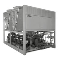
AIR-COOLED SCROLL CHILLERS WITH MICROCHANNEL CONDENSER COILS STYLE A (50 HZ) 57 - 142 TON
Brand:
York
| Category:
Chiller
| Size: 10 MB
Table of Contents
Table of Contents
4
Section 1 - General Chiller Information & Safety
13
Introduction
13
Warranty
13
Safety and Quality
13
Standards for Safety and Quality
13
Responsibility for Safety
14
About this Manual
14
Misuse of Equipment
14
Suitability for Application
14
Structural Support
14
Mechanical Strength
14
General Access
14
Pressure Systems
15
Electrical
15
Rotating Parts
15
Sharp Edges
15
Refrigerants and Oils
15
High Temperature and Pressure Cleaning
15
Emergency Shutdown
15
Section 2 - Product Description
17
Introduction
17
General System Description
17
Compressors
17
Cooler (Evaporator)
17
Condenser
18
High Ambient Kit
19
Building Automation System Interface
19
Power Panel
19
Accessories and Options
20
Power Options
20
Control Options
20
Compressor, Piping, Evaporator Options
20
Condenser and Cabinet Options
21
Unit Components
23
Fig. 1 - Unit Components Front
23
Fig. 2 - Unit Components Side
24
Control / Power Panel Components
25
Fig. 3 - Power Panel Components
25
Fig. 4 - Power Panel / Control Components
26
Product Identification Number (Pin)
27
Basic Unit Nomenclature
27
Fig. 5 - Refrigerant Flow Diagram
33
Process and Instrumentation Diagram
34
Fig. 6 - Process and Instrumentation Diagram
34
Section 3 - Handling and Storage
35
Delivery and Storage
35
Inspection
35
Moving the Chiller
35
Lifting Weights
35
Fig. 7 - Unit Rigging/Lifting
36
Section 4 - Installation
37
Installation Checklist
37
Handling
37
Inspection
37
Location and Clearances
37
Foundation
38
Ground Level Locations
38
Rooftop Locations
38
Noise Sensitive Locations
38
Spring Isolators (Optional)
38
Compressor Mounting
38
Remote Cooler Option
38
Chilled Liquid Piping
38
Pipework Arrangement
39
Fig. 8 - Chilled Liquid System
39
Duct Work Connection
40
General Requirements
40
Wiring
40
Evaporator Pump Start Contacts
40
System Run Contacts
40
Alarm Status Contacts
41
Remote Start/Stop Contacts
41
Remote Emergency Cutoff
41
Remote Temp Reset Input
41
Load Limit Input
41
Flow Switch Input
41
Compressor Heaters
41
Relief Valves
41
High Pressure Cutout
41
Single-Point Supply Connection - Terminal Block, Non-Fused Disconnect Switch or Circuit Breaker
42
Fig. 9 - Single-Point Supply Connection - Terminal Block, Non-Fused Disconnect Switch or Circuit Breaker
42
User Control Wiring Inputs
43
Fig. 10 - Control Wiring Inputs
43
User Control Wiring Outputs
44
Fig. 11 - Control Wiring Outputs
44
Section 5 - Technical Data
45
Operational Limitations (English)
45
Temperatures and Flows
45
Voltage Limitations
45
Table 1 - Temperatures and Flows
45
Table 2 - Voltage Limitations
45
Heat Exchanger Flow, Gpm
46
Ethylene & Propylene Glycol Correction Factors
46
Table 3 - Ethylene & Propylene Glycol Correction Factors
46
Physical Data (English)
47
Standard Efficiency YLAA0285 - YLAA0485
47
Table 4 - Physical Data (English)
47
High Efficiency YLAA0195 - YLAA0515
48
Table 4A - Physical Data (English)
48
Electrical Information
49
Table 5 - Micropanel Power Supply
49
Table 6 - Voltage Range
49
Electrical Notes
50
Electrical Data
51
Wiring Lugs
52
Electrical Notes and Legend
53
Wiring Diagrams
56
Elementary Wiring Diagrams - YLAA0195
56
Fig. 12 - Elementary Wiring Diagram, Ylaa0195 Sht 1
56
Fig. 13 - Elementary Wiring Diagram, Ylaa0195 Sht 2
58
Fig. 14 - Elementary Wiring Diagram, Ylaa0195 Sht 3
60
Fig. 15 - Elementary Wiring Diagram, Ylaa0195 Sht 4
62
Fig. 16 - Elementary Wiring Diagram, Ylaa0195 Sht 5
64
Fig. 17 - Elementary Wiring Diagram, Ylaa0195 Sht 6
66
Fig. 18 - Elementary Wiring Diagram, Ylaa0195 Sht 7
68
Fig. 19 - Elementary Wiring Diagram, Ylaa0195 Sht 8
70
Fig. 20 - Elementary Wiring Diagram, Ylaa0195 Sht 9
72
Connection Wiring Diagrams - YLAA0195
74
Fig. 21 - Connection Wiring Diagram, Ylaa0195 Sht 1
74
Fig. 22 - Connection Wiring Diagram, Ylaa0195 Sht 2
76
Fig. 23 - Connection Wiring Diagram, Ylaa0195 Sht 3
78
Fig. 24 - Connection Wiring Diagram, Ylaa0195 Sht 4
80
Fig. 25 - Connection Wiring Diagram, Ylaa0195 Sht 5
82
Fig. 26 - Connection Wiring Diagram, Ylaa0195 Sht 6
84
Fig. 27 - Connection Wiring Diagram, Ylaa0195 Sht 7
86
Elementary Wiring Diagrams - YLAA0220 - YLAA0515
88
Fig. 28 - Elementary Wiring Diagram, Ylaa0220 - Ylaa0515, Sht 1
88
Fig. 29 - Elementary Wiring Diagram, Ylaa0220 - Ylaa0515, Sht 2
90
Fig. 30 - Elementary Wiring Diagram, Ylaa0220 - Ylaa0515, Sht 3
92
Fig. 31 - Elementary Wiring Diagram, Ylaa0220 - Ylaa0515, Sht 4
94
Connection Diagrams - YLAA0220 - YLAA0515
96
Fig. 32 - Connection Diagram, Ylaa0220 - Ylaa0515, Sht 1
96
Fig. 33 - Connection Diagram, Ylaa0220 - Ylaa0515, Sht 2
98
Fig. 34 - Connection Diagram, Ylaa0220 - Ylaa0515, Sht 3
100
Fig. 35 - Connection Diagram, Ylaa0220 - Ylaa0515, Sht 6
102
Fig. 36 - Connection Diagram, Ylaa0220 - Ylaa0515, Sht 7
104
Fig. 37 - Wiring Diagram, Single Point Wiring Options
106
Fig. 38 - Dual Pump Wiring
107
Fig. 39 - Wiring
108
Fig. 40 - Layout - Power Blocks and Transformers
110
Dimensions (English)
111
Fig. 41 - Dimensions (English) Ylaa0195He
111
Fig. 42 - Dimensions (English) Ylaa0220He, 0260He, 0285Se, & 320Se
112
Fig. 43 - Dimensions (English) Ylaa0300He,Ylaa0360Se, Ylaa0400Se
113
Fig. 44 - Dimensions (English) Ylaa0435Se (English)
114
Fig. 45 - Dimensions (English) Ylaa0350He (English)
115
Fig. 46 - Dimensions (English) Ylaa0390He, Ylaa0485Se
116
Fig. 47 - Dimensions (English) Ylaa0440He
117
Fig. 48 - Dimensions (English) Ylaa0455He
118
Fig. 49 - Dimensions (English) Ylaa0515He
119
Technical Data - Clearances
120
Fig. 50 - Unit Clearances - All Models
120
Weight Distribution and Isolator Mounting Positions
121
Fig. 51 - Weight Distribution and Isolator Mounting Positions
121
Isoloator Data
124
One Inch Deflection Spring Isolator Cross-Reference
124
Fig. 52 - One Inch Deflection Spring Isolator Cross-Reference
124
One Inch Deflection Spring Isolators Installation Instructions
125
Fig. 53 - One Inch Deflection Spring Isolators Installation Instructions
125
Seismic Isolator Cross-Reference
126
Fig. 54 - Seismic Isolator Cross-Reference
126
Seismic Isolator Installation and Adjustment INSTRUCTIONS
127
Fig. 55 - Seismic Isolator Installation and Adjustment Instructions
127
Duralene Isolator Cross-Reference
128
Fig. 56 - Duralene Isolator Cross-Reference
128
Installation of Durulene Vibration Isolators INSTRUCTIONS
129
Fig. 57 - Installation of Durulene Vibration Isolators Instructions
129
Section 6 - Commissioning
131
Commissioning
131
Preparation - Power off
131
Inspection
131
Refrigerant Charge
131
Service and Oil Line Valves
131
Compressor Oil
131
Fans
131
Isolation / Protection
131
Control Panel
131
Supply Voltage
132
Preparation - Power on
132
Switch Settings
132
Compressor Heaters
132
Water System
132
Flow Switch
132
Temperature Sensor(S)
132
Equipment Pre-Startup & Startup Checklist
133
Pre-Startup
133
Startup
133
Setpoints Entry List
134
Table 7 - Setpoints Entry List
134
Checking Superheat and Subcooling
135
Leak Checking
135
Unit Operating Sequence
136
Section 7 - Unit Controls
137
Introduction
137
IPU II and I/O Boards
137
Display
138
Keypad
138
Battery Back-Up
138
Transformer
138
Programming # of Compressors
138
Status" Key
139
Unit Status
139
General Status Messages
139
Fault Safety Status Messages
141
Status Key Messages
144
Table 8 - Status Key Messages Quick Reference List
144
Display/Print Keys
145
Oper Data Key
145
Oper Data Quick Reference List
148
Table 9 - Operation Data
148
Print Key
149
Operating Data Printout
149
History Printout
150
History Displays
150
Software Version
152
Entry" Keys
153
Up and down Arrow Keys
153
Enter/Adv Key
153
Setpoints" Keys
154
Cooling Setpoints
154
Leaving Chilled Liquid Control
154
Return Chilled Liquid Control
155
Remote Setpoints Control
155
Schedule/Advance Day Key
155
Table 10 - Cooling Setpoints, Programmable Limits and Defaults
156
Program Key
157
System Trip Volts
158
Unit Trip Volts
159
Program Key Limits and Default
159
Table 11 - Program Key Limits and Default
159
Setpoints Quick Reference List
160
Table 12 - Setpoints Quick Reference List
160
Unit" Keys
161
Options Key
161
Clock
165
Unit Keys Options Programming Quick Reference List
166
Table 13 - Unit Keys Options Programming Quick Reference List
166
Section 8 - Unit Operation
167
Capacity Control
167
Suction Pressure Limit Controls
167
Discharge Pressure Limit Controls
167
Leaving Chilled Liquid Control
167
Leaving Chilled Liquid System Lead/Lag and Compressor Sequencing
168
Leaving Chilled Liquid Controloverride to Reduce Cycling
168
Fig. 58 - Leaving Water Temperature Control Example
168
Fig. 59 - Setpoint Adjust
168
Return Chilled Liquid Control
169
Table 14 - Sample Compressor Staging for Return Water Control
169
Return Chillled Liquid System Lead/Lag and Compressor Sequencing
170
Table 15 - Return Chilled Liquid Control for 4 Compressors (6 Steps)
170
Table 16 - Return Chilled Liquid Control for 4 Compressors (6 Steps)
170
Anti-Recycle Timer
171
Anti-Coincidence Timer
171
Evaporator Pump Control & York
171
Hydro Kit Pump Control
171
Evaporator Heater Control
171
Pumpdown Control
171
Standard Condenser Fan Control
171
Fig. 60 - Condenser Fan Locations Wiring Diagrams
172
Only (2, 3, or 4 Fans Per System)
173
Table 17 - Ylaa Standard Condenser Fan Control Using Discharge Pressure
173
Only (5 or 6 Fans Per System)
174
Table 18 - Ylaa Standard Condenser Fan Control Using Discharge Pressure
174
Alarm Status
175
Compressor Run Status
175
Load Limiting
175
Table 19 - Compressor Operation - Load Limiting
175
Bas/Ems Temperature Reset Usinga Voltage or Current Signal
176
Section 9 - Service and Troubleshooting
177
Clearing History Buffers
177
Service Mode
177
Service Mode - Outputs
177
Service Mode - Chiller Configuration
178
Service Mode - Analog & Digital Inputs
178
Control Inputs/Outputs
179
Table 20 - I/O Digital Inputs
179
Table 21 - I/O Digital Outputs
179
Table 22 - I/O Analog Inputs
179
Table 23 - I/O Analog Outputs
179
Microboard Layout
180
Fig. 61 - Microboard Layout
180
Checking Inputs and Outputs
181
Digital Inputs
181
Analog Inputs - Temperature
181
Outside Air Sensor
181
Table 24 - Outdoor Air Sensor
181
Liquid & Refrigerant Sensor Test Points
182
Table 25 - Entering/Leaving Chilled Liquid Temp. Sensor, Temperature/Voltage Correlation
182
Analog Inputs - Pressure
183
Table 26 - Pressure Transducers
183
Digital Outputs
184
Fig. 62 - I/O Board Relay Contact Architecture
184
Optional Printer Installation
185
Parts
185
Assembly and Wiring
185
Obtaining a Printout
185
Fig. 63 - Printer to Microboard Electrical Connections
185
Troubleshooting
186
Table 27 - Troubleshooting
186
Section 10 - Maintenance
189
Important
189
Compressors
189
Oil Level Check
189
Oil Analysis
189
Condenser Fan Motors
189
Condenser Coils
189
Operating Parameters
189
On-Board Battery Back-Up
189
Plate and Frame Heat Exchanger (Evaporator) Heater
189
Microchannel Coil Cleaning
190
Bacnet, Modbus and Yorktalk 2 Communications
191
Fig. 64 - Micropanel Connections
192
Table 28 - Minimum, Maximum and Default Values
192
Table 29 - Values Required for Bas Communication
193
Table 30 - Real Time Error Numbers
193
Bacnet and Modbus Communications
194
Communications Data Map Notes
194
Table 31 - Bacnet and Modbus Communications Data Map
195
Yorktalk 2 Communications
198
Received Data (Control Data)
198
Transmitted Data
198
Table 32 - Yorktalk 2 Communications Data Map
199
Temperature Conversion Chart
202
R410Apressure Temperature Chart
203
Advertisement
York YLAA0435SE Installation Operation & Maintenance (186 pages)
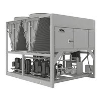
AIR-COOLED SCROLL CHILLERS WITH BRAZED PLATE HEAT EXCHANGER STYLE B (50 HZ) 4-8 FAN
Brand:
York
| Category:
Chiller
| Size: 11 MB
Table of Contents
Table of Contents
5
Section 1 - General Chiller Information and Safety
11
Introduction
11
Warranty
11
Handling
11
Safety and Quality
11
About this Manual
12
Misuse of Equipment
12
Section 2 - Product Description
15
Introduction
15
General System Description
15
Communications
17
Building Automation System Interface
17
Power Panel
17
Accessories and Options
17
FIGURE 1 - Unit Components (Front)
20
FIGURE 2 - Unit Components (Side)
21
FIGURE 3 - Power Panel Components
22
FIGURE 4 - Power Panel / Control Components
23
TABLE 1 - Complete Pin Number Description
24
FIGURE 5 - Process and Instrumentation Diagram
29
Section 3 - Handling and Storage
31
Delivery and Storage
31
Inspection
31
Moving the Chiller
31
Lifting Weights
32
Lifting Using Lugs
33
Lifting Using Shackles
33
FIGURE 6 - Unit Rigging/Lifting
34
Section 4 - Installation
35
Installation Checklist
35
Startup/Commissioning
35
Location and Clearances
35
Spring Isolators (Optional)
36
Compressor Mounting
36
Chilled Liquid Piping
36
Pipework Arrangement
37
Wiring
37
FIGURE 7 - Chilled Liquid System
37
Relief Valves
38
High Pressure Cutout
38
Single-Point Supply Connection - Terminal Block, Non-Fused Disconnect Switch, or Circuit Breaker
39
FIGURE 8 - Single-Point Supply Connection - Terminal Block, Non-Fused Disconnect Switch, or Circuit
39
FIGURE 9 - Control Wiring Inputs
40
FIGURE 10 - Thermal Dispersion Flow Switch
41
FIGURE 11 - Thermal Dispersion Flow Switch (Combine Together)
41
FIGURE 12 - Control Wiring Outputs
43
Section 5 - Technical Data
45
Operational Limitations
45
TABLE 2 - Temperatures and Flows
45
TABLE 3 - Ethylene and Propylene Glycol Correction Factors
47
Physical Data YLAA0180 - YLAA0517 50 Hz
48
TABLE 4 - Physical Data (English) - Standard Efficiency Units
48
TABLE 5 - Physical Data (English) - High Efficiency Units
49
Electrical Data
51
Compressor Heaters
51
TABLE 6 - Micropanel Power Supply
51
TABLE 7 - Voltage Range
51
TABLE 8 - Electrical Data Without Pumps
52
TABLE 9 - Pump Electrical Data (50 Hz)
53
TABLE 10 - Transformer Load
53
TABLE 11 - Wiring Lugs
54
Electrical Notes
55
FIGURE 13 - Elementary Wiring Diagram
60
FIGURE 14 - Elementary Wiring Diagram
62
FIGURE 15 - Fan Wiring, Standard Low Sound or Ultra Quiet, YLAA0180 - YLAA0517
64
FIGURE 16 - Fan Wiring, High Air Flow
66
FIGURE 17 - Single and Dual Point Wiring Options
68
FIGURE 18 - Pump Wiring
69
FIGURE 19 - Connection - EEV Option
70
FIGURE 20 - Compressor Wiring
72
FIGURE 21 - Power Options Connection Diagram
74
FIGURE 22 - Power Panel
76
FIGURE 23 - Micro Panel Connections
79
Weight Distribution and Isolator Mounting Positions
86
FIGURE 24 - Sample Printout Supplied in the Isolator Package and in the Chiller Panel Literature Packet
86
Clearances
87
FIGURE 25 - Unit Clearances - All Models
87
Four Fan Isolator Locations
88
Five and Six Fan Isolator Locations
88
Seven and Eight Fan Isolator Locations
89
Isolator Information
90
Section 6 - Commissioning
97
Preparation - Power off
97
FIGURE 26 - LED Indicator Buttons
99
FIGURE 27 - Flow Switch Set
100
FIGURE 28 - Flow below the Representation Range
100
FIGURE 29 - Flow Exceeds the Representation Range
100
Preparation - Power on
101
FIGURE 30 - EEV IB-G Interface Board
101
Section 7 - Unit Controls
105
Introduction
105
IPU II and I/O Boards
105
Transformer
106
Display
106
Keypad
106
Unit Switch
106
Battery Back-Up
106
Programming # of Compressors
106
Status Key
107
TABLE 12 - YLAA Fault and Inhibit Codes
112
TABLE 13 - Legend
112
FIGURE 31 - Status Key Messages Quick Reference List
113
Display/Print Keys
114
FIGURE 32 - Operation Data
117
Entry Keys
122
Set Points Keys
123
Schedule/Advance Day Key
124
TABLE 14 - Cooling Set Point, Programmable Limits, and Defaults
125
Program Key
126
TABLE 15 - Program Key Limits and Default
128
FIGURE 33 - Set Points Quick Reference List
129
TABLE 16 - Program Key Limits and Default
130
Unit Keys
132
FIGURE 34 - Unit Keys Options Programming Quick Reference List
139
Bacnet, Modbus, N2, and Yorktalk 2 Communications
140
FIGURE 35 - Micro Panel Connections
141
TABLE 17 - Minimum, Maximum and Default Values
141
TABLE 18 - Values Required for BAS Communication
142
TABLE 19 - Real Time Error Numbers
143
TABLE 20 - Native Bacnet, Modbus, and N2 Communications Data Map
144
TABLE 21 - Yorktalk 2 Communications Data Map
148
Section 8 - Unit Operation
155
Capacity Control
155
Suction Pressure Limit Controls
156
Discharge Pressure Limit Controls
156
Leaving Chilled Liquid Control
156
FIGURE 36 - Leaving Water Temperature Control Example
156
Leaving Chilled Liquid Control Override to Reduce Cycling
157
FIGURE 37 - Set Point Adjust
157
TABLE 22 - Sample Compressor Staging for Return Water Control
157
TABLE 23 - Return Chilled Liquid Control for 4 Compressors (6 Steps)
157
Leaving Chilled Liquid System Lead/Lag and Compressor Sequencing
158
Return Chilled Liquid Control
158
TABLE 24 - Lead/Lag Return Chilled Liquid Control for 4 Compressors (6 Steps)
158
Return Chilled Liquid System Lead/Lag and Compressor Sequencing
159
Anti-Recycle Timer
159
Anti-Coincidence Timer
160
Evaporator Pump Control and York Hydro Kit Pump Control
160
Evaporator Heater Control
160
Pumpdown Control
160
Standard Condenser Fan Control
160
VSD Fan
161
Changing the Switch Point of the Thermal Dispersion Flow Switch
161
FIGURE 38 - Condenser Fan Locations
161
TABLE 25 - YLAA Standard Condenser Fan Control Using Discharge Pressure Only (2, 3, or 4 Fans Per System)
162
TABLE 26 - YLAA Standard Condenser Fan Control Using Discharge Pressure Only
163
Load Limiting
164
Compressor Run Status
164
Alarm Status
164
TABLE 27 - Compressor Operation Load Limiting
164
Remote BAS/EMS Temperature Reset Using a Voltage or Current Signal
165
Section 9 - Service and Troubleshooting
167
Clearing History Buffers
167
Service Mode
167
Service Mode - Outputs
167
Service Mode - Chiller Configuration
168
Service Mode - Analog and Digital Inputs
168
Control Inputs/Outputs
169
TABLE 28 - I/O Digital Inputs
169
TABLE 29 - I/O Digital Outputs
169
TABLE 30 - I/O Analog Inputs
169
TABLE 31 - I/O Analog Outputs
169
FIGURE 39 - Microboard Layout
170
Checking Inputs and Outputs
171
TABLE 32 - Outdoor Air Sensor Temperature/Voltage/Correlation
171
TABLE 33 - Entering/Leaving Chilled Liquid Temp. Sensor, Temperature/Voltage Correlation
172
TABLE 34 - Pressure Transducers
173
FIGURE 40 - I/O Board Relay Contact Architecture
174
TABLE 35 - Data Logging to Flash
175
Optional Printer Installation
177
FIGURE 41 - Printer to Microboard Electrical Connections
178
Troubleshooting
179
TABLE 36 - Troubleshooting
179
Section 10 - Maintenance
181
Compressors
181
Condenser Fan Motors
181
Condenser MCHX Cleaning
181
Operating Parameters
182
On-Board Battery Back-Up
182
Thermal Dispersion Flow Switch
182
Brazed Plate Heat Exchanger (Evaporator) Heater
182
Overall Unit Inspection
182
Temperature
185
TABLE 37 - si Metric Conversion
185
Advertisement
Related Products
York YLAA0400SE
York YLAA0485SE
York YLAA0440HE
York YLAA0445HE
York YLAA0442HE
York YLAA0457HE
York YLAA0442
York YLAA0457
York YLAA0175
York YLAA0285SE
York Categories
Air Conditioner
Heat Pump
Chiller
Furnace
Air Handlers
More York Manuals
Login
Sign In
OR
Sign in with Facebook
Sign in with Google
Upload manual
Upload from disk
Upload from URL