
Related Manuals for Aerotech BM


Summary of Contents for Aerotech BM
- Page 1 (217) 352-9330 | Click HERE Find the Aerotech BM75 at our website:...
- Page 2 BM/BMS Brushless Motor Hardware Manual P/N: EDA135 (Revision 2.06.00) Dedicated to the Science of Motion Aerotech, Inc. 101 Zeta Drive, Pittsburgh, PA, 15238 Phone: 412-963-7470 Fax: 412-963-7459 www.aerotech.com Artisan Technology Group - Quality Instrumentation ... Guaranteed | (888) 88-SOURCE | www.artisantg.com...
- Page 3 The most recent system drawings and schematics can be found on your software CD ROM or on www.aerotech.com. N O T E : This manual and any additional instructions included with the BM/BMS should be read in their entirety before operating the BM/BMS .
-
Page 4: Table Of Contents
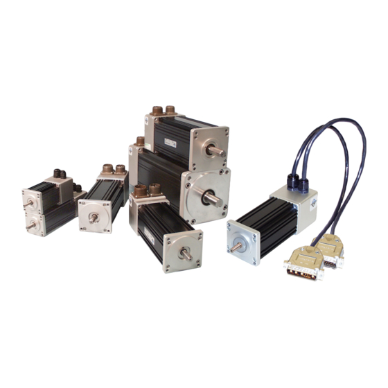
BM/BMS Brushless Motor Hardware Manual Table of Contents Table of Contents Chapter 1: BM/BMS Brushless Motor Hardware Manual 1.1. EC Declaration of Conformity 1.2. Safety Procedures and Warnings 1.3. Motor Installation 1.3.1. Connector Pin Assignment 1.4. External Motor Wiring 1.4.1. Motor Power Conductors 1.4.2. - Page 5 Table of Contents BM/BMS Brushless Motor Hardware Manual List of Figures Figure 1-1: BM/BMS Series Brushless Motors Figure 1-2: Typical Thermal Sensor Resistance as a Function of Temperature Figure 1-3: Typical Thermistor Interface Circuit Figure 1-4: Hall Effect and Motor Phasing...
- Page 6 BM/BMS Brushless Motor Hardware Manual Table of Contents List of Tables Table 1-1: Motor Power Connector Pin Assignment (MS3101A-18-10P) Table 1-2: Feedback Connector Pin Assignment (MS3101A-20-29P) Table 1-3: Resolver Connector Pin Assignment (MS3101A-20-29P) Table 1-4: 9-Pin D-Connector Pin Assignment Table 1-5:...
- Page 7 Table of Contents BM/BMS Brushless Motor Hardware Manual www.aerotech.com Artisan Technology Group - Quality Instrumentation ... Guaranteed | (888) 88-SOURCE | www.artisantg.com...
-
Page 8: Chapter 1: Bm/Bms Brushless Motor Hardware Manual
This makes them ideal for critical applications where downtime cannot be tolerated. In addi- tion, the BM series motors have very high power density resulting in high torque in a compact package. Optional IP65 sealing make these motors ideal for harsh environments such as machine tool and even in wash down applications such as food processing. -
Page 9: Ec Declaration Of Conformity
BM/BMS Brushless Motors BM/BMS Brushless Motor Hardware Manual 1.1. EC Declaration of Conformity Manufacturer Aerotech, Inc. Address 101 Zeta Drive Pittsburgh, PA 15238 Product BMS (excluding VAC6 versions) Model/Types This is to certify that the aforementioned product is in accordance with the applicable requirements of the fol-... -
Page 10: Safety Procedures And Warnings
Rear View N O T E : BM/BMS motors (all Aerotech equipment) are not to be used in a manner not specified by Aero- tech, Inc. W A R N I N G : The BM/BMS Servo Motors are not intended to be directly connected to an electrical power distribution system. - Page 11 ROM or on www.aerotech.com. N O T E : Aerotech continually improves its product offerings; listed options may be superseded at any time. Refer to the most recent edition of the Aerotech Motion Control Product Guide for the most current product information at www.aerotech.com.
-
Page 12: Motor Installation
BM/BMS Brushless Motor Hardware Manual BM/BMS Brushless Motors 1.3. Motor Installation Motors are installed by bolting the motor flange to a mounting surface using four holes on the motor flange. The load is connected to the motor shaft using keyways and/or flats. -
Page 13: Table 1-3: Resolver Connector Pin Assignment (Ms3101A-20-29P)
BM/BMS Brushless Motors BM/BMS Brushless Motor Hardware Manual Table 1-3: Resolver Connector Pin Assignment (MS3101A-20-29P) Function Sine + Sine - Cosine + Cosine - Ref + Ref - Sine Shield (no connection to frame) Cosine Shield (no connection to frame) -
Page 14: Table 1-5: 25-Pin D-Connector Pin Assignment
BM/BMS Brushless Motor Hardware Manual BM/BMS Brushless Motors Table 1-5: 25-Pin D-Connector Pin Assignment Label Description Connector SIG SHLD Signal shield connection Thermistor Over-temperature Thermistor Sensor Encoder +5V +5 V supply input for optical encoders (the typical require- ment is 250 mA). -
Page 15: External Motor Wiring
Fuse values should be selected according to the RMS current rating of the motor. For most applications slow-blow type fuses should be used. When the motor is part of an Aerotech system utilizing an Aerotech controller and drive, the “A ” continuous current rating of the motor must be used to set the motor over-current protection fault. -
Page 16: Hall-Effect Device And Thermistor Wiring
BM/BMS Brushless Motor Hardware Manual BM/BMS Brushless Motors 1.4.4. Hall-Effect Device and Thermistor Wiring The insulation of these wires should have a rating for at least the maximum voltage applied to the motor wind- ing. The temperature rating of the wire insulation must also be sufficiently high to withstand the operating temperatures specific to the application. -
Page 17: Thermal Protective Device
BM/BMS Brushless Motors BM/BMS Brushless Motor Hardware Manual 1.4.6. Thermal Protective Device BMS motors incorporate a positive-temperature coefficient (PTC) thermistor as a thermal protection device. The nominal resistance of the thermistor is 100 ohms at 25°C. The thermistor exhibits a rapid increase in resistance to 1,000 ohms as the motor temperature approaches the thermistor’s transition temperature of... -
Page 18: Figure 1-3: Typical Thermistor Interface Circuit
BM/BMS Brushless Motor Hardware Manual BM/BMS Brushless Motors This thermistor can be used in a variety of different electronic interfaces. A precaution when using this type of device in an interface circuit is to avoid self-heating effects. An excessive amount of current through the thermistor will cause its temperature to rise. -
Page 19: Hall-Effect Operation And Motor Phasing
BM/BMS Brushless Motors BM/BMS Brushless Motor Hardware Manual 1.5. Hall-Effect Operation and Motor Phasing Aerotech brushless motors are shipped from the factory with the correct motor phase to Hall effect rela- tionship. Figure 1-4 shows the proper Hall effect to motor phasing for both clockwise (CW) and counter- clockwise (CCW) motor rotation viewed as shown. -
Page 20: Figure 1-5: Test Setup Configuration
Note the peak of the sine wave of channel 3 in comparison to the peak of the sine wave of channel 1. Aerotech phasing expects ØC to be the lead signal in time, ØB to follow it, and ØA to follow ØB. This means that whichever signal has been determined to lead the others in time is designated as the ØC winding. -
Page 21: Figure 1-6: Motor Lead Phasing With Oscilloscope
BM/BMS Brushless Motors BM/BMS Brushless Motor Hardware Manual Channel 1 at TP1 and Channel 2 at TP2 Channel 1 at TP1 and Channel 2 at TP3 (TP2) (TP3) (TP1) (TP1) In this example: Signals Combined for Comparison The peak of the sine wave signal at TP2 precedes the peaks of the sine wave signals at TP1 and TP3. -
Page 22: Figure 1-7: Hall Phasing With Oscilloscope
BM/BMS Brushless Motor Hardware Manual BM/BMS Brushless Motors Channel 1 at TP1 and Channel 2 at TP5, TP6, and TP7 CHANNEL 1 (CH2) Hall (CH2) (CH2) Power Supply ØB (CH1) Channel 1 at TP2 and Channel 2 at TP5, TP6, and TP7... -
Page 23: Resolver Commutation
BM/BMS Brushless Motors BM/BMS Brushless Motor Hardware Manual 1.6. Resolver Commutation An optional resolver can be used as the feedback device for the motor. The resolver is aligned at the factory such that the null position of the resolver corresponds to a motor phase angle of zero degrees (refer to Figure 1-8). -
Page 24: Motor Heating
BM/BMS Brushless Motor Hardware Manual BM/BMS Brushless Motors 1.7. Motor Heating The temperature rise above ambient establishes a limit on the amount of current allowed through the motor winding. The thermal characteristics of the motor, the effectiveness of the surrounding medium to transfer heat away from the motor, and any supplemental cooling determine the operating conditions. -
Page 25: Maintenance
BM/BMS Brushless Motors BM/BMS Brushless Motor Hardware Manual 1.8. Maintenance Installation problems usually reveal themselves early in the installation. Regular preventative maintenance should include but is not limited to the following: make frequent checks for excessive or abnormal motor heat- ing, excessive motor vibrations, loose motor to machine couplers, obstructed air flow to the motor, burning smells, an accumulation of debris on the motor, etc. -
Page 26: Environmental Specifications
The motors are not to be used in wash-down environments (unless ordering with the IP65 option). Dust Exposure: The BM and BMS motors are rated IP40. The BM250, 500, 800, 1400, and 2000 can be ordered, as an option, with IP65 protection. Altitude: Up to 2000 m. -
Page 27: Motor Specifications
(6) Maximum winding temperature is 155 °C (7) Ambient operating temperature range: 0 °C - 25 °C, consult Aerotech for performance in elevated ambient temperatures (8) De-rate continuous torque and continuous current by 10 percent when using an encoder(does not apply to BM22) (9) All Aerotech amplifiers are rated A ;... -
Page 28: Table 1-7: Bm250 And Bm500 Motor Specifications
(6) Maximum winding temperature is 155 °C (7) Ambient operating temperature range: 0 °C - 25 °C, consult Aerotech for performance in elevated ambient temperatures (8) De-rate continuous torque and continuous current by 10 percent when using an encoder(does not apply to BM22) (9) All Aerotech amplifiers are rated A ;... -
Page 29: Table 1-8: Bm800, Bm1400 Motor Specifications
(6) Maximum winding temperature is 155 °C (7) Ambient operating temperature range: 0 °C - 25 °C, consult Aerotech for performance in elevated ambient temperatures (8) De-rate continuous torque and continuous current by 10 percent when using an encoder(does not apply to BM22) (9) All Aerotech amplifiers are rated A ;... -
Page 30: Table 1-9: Bm2000, Bm3400, Bm4500 Motor Specifications
(6) Maximum winding temperature is 155 °C (7) Ambient operating temperature range: 0 °C - 25 °C, consult Aerotech for performance in elevated ambient temperatures (8) De-rate continuous torque and continuous current by 10 percent when using an encoder(does not apply to BM22) (9) All Aerotech amplifiers are rated A ;... -
Page 31: Table 1-10: Bms35, Bms60, Bms100 Motor Specifications
(5) All performance and electrical specifications +/- 10% (6) Maximum winding temperature is 100 °C (Thermistor trips at 100°C) (7) Ambient operating temperature range: 0 °C - 25 °C, consult Aerotech for performance in elevated ambient temperatures (8) All Aerotech amplifiers are rated A ;... -
Page 32: Table 1-11: Bms280, Bms465 Motor Specifications
(5) All performance and electrical specifications +/- 10% (6) Maximum winding temperature is 100 °C (Thermistor trips at 100°C) (7) Ambient operating temperature range: 0 °C - 25 °C, consult Aerotech for performance in elevated ambient temperatures (8) All Aerotech amplifiers are rated A ;... -
Page 33: Brushless Motor Dimensions
BM/BMS Brushless Motors BM/BMS Brushless Motor Hardware Manual 1.11. Brushless Motor Dimensions The following figures show the outline dimensions of each model in BM series brushless motors. 91.1±1 [3.59±.04] 24±1 [.94±.04] 31 [1.22] Add 36.9 [1.45] For Brake Option Square 2 [.08]... -
Page 34: Figure 1-11: Bm75, Bm130, Bm200 Model Dimensions (Nema 23)
BM/BMS Brushless Motor Hardware Manual BM/BMS Brushless Motors 2 Flats At 90° Apart 0.5 [0.02] Ø5.0 [Ø0.20] 47.1 [1.86] Typ. 4 Holes Square 16.0 [0.63] 53.1 [2.09] Shaft Dia. +0.00 Ø38.10 -0.03 57.2 [2.25] +0.000 [Ø1.500 Cable Lengths Vary Square -0.001... -
Page 35: Figure 1-13: Bm800, Bm1400 Model Dimensions (Nema 42)
BM/BMS Brushless Motors BM/BMS Brushless Motor Hardware Manual 108.0 [4.25] Square Ø7.1 [Ø0.28] Thru 4 Holes 88.9 [3.50] 50.8 [2.00] Square 13.2 [0.52] Shaft Dia. +0.00 44.5 [1.75] Ø55.55 -0.03 2 Flats +0.000 [ Ø2.187 -0.001 90° Apart Typ. 130.2 [5.13] 1.0 [0.04]... -
Page 36: Figure 1-15: Bms35 Model Dimensions (Nema 17)
BM/BMS Brushless Motor Hardware Manual BM/BMS Brushless Motors +.0000 0.000 Ø6.345 .2498 -.0005 0.013 13.8 [.55] 35.9 [1.41] Ø4.0 [.16] Square Slot 5.0 [.20] 37.0 [1.46] 44.5 [1.75] +.000 0.00 Square Square Ø22.00 .866 -.001 0.03 2.3 [.09] 20.6 [.81] 14.4 [.57]... -
Page 37: Figure 1-17: Bms280 And Bms465 Model Dimensions (Nema 34)
BM/BMS Brushless Motors BM/BMS Brushless Motor Hardware Manual 82.6 [3.25] Sq. 5.6 [0.22]Dia. 69.6 [2.74] Sq. Thru 4 Holes 30.2 [1.19] 1/8 [3.2] Sq Keyway By 0.88 [22.4] Lg. 11.4 [0.45] Shaft Dia. +0.00 Ø73.03 -0.03 +0.000 [Ø 2.875 -0.001 108.0 [4.25]... -
Page 38: Part Number And Ordering Information
MS Motor Power connector [IEC 142] MCM-3 MS Motor Power connector [NEMA 23, NEMA 34, NEMA 42] MCF-3 MS Motor Feedback connector for all BM motors www.aerotech.com Chapter 1 Artisan Technology Group - Quality Instrumentation ... Guaranteed | (888) 88-SOURCE | www.artisantg.com... -
Page 39: Table 1-13: Bms Motor Options
BM/BMS Brushless Motors BM/BMS Brushless Motor Hardware Manual Table 1-13: BMS Motor Options BMS Series Rotary Servo Motors BMS35 NEMA 17 brushless servomotor; 38.0 oz·in continuous torque BMS60 NEMA 23 brushless servomotor; 46.2 oz·in continuous torque BMS100 NEMA 23 brushless servomotor; 80.0 oz·in continuous torque BMS280 NEMA 34 brushless servomotor;... -
Page 40: Appendix A: Warranty And Field Service
Aerotech in specifications or draw- ings previously or subsequently provided, or whether or not Aerotech's products are specifically designed and/or manufactured for buyer's use or purpose. - Page 41 Warranty and Field Service BM/BMS Brushless Motor Hardware Manual On-site Warranty If an Aerotech product cannot be made functional by telephone assistance or by Repair sending and having the customer install replacement parts, and cannot be returned to the Aerotech service center for repair, and if Aerotech determines the...
-
Page 42: Appendix B: Revision History
BM/BMS Brushless Motor Hardware Manual Technical Changes Appendix B: Revision History Revision Date General Information 2.06.00 July 25, 2012 Added BMS35, updating: Section 1.10. Section 1.11. Section 1.12. Updated connector pin tables: Section 1.3.1. Updated Thermal Sensor Resistance: Figure 1-2 Updated BMS35 specification (Rated Power Output, Cont): Table 1-10... - Page 43 Technical Changes BM/BMS Brushless Motor Hardware Manual Appendix B www.aerotech.com Artisan Technology Group - Quality Instrumentation ... Guaranteed | (888) 88-SOURCE | www.artisantg.com...
-
Page 44: Index
BM Motor Options 31 BMS465 Model Dimensions (NEMA 34) 30 BM Series 1 BMS465 Motor Specifications 25 BM/BMS Brushless Motor Hardware Manual 1 BMS60 Model Dimensions (NEMA 23) 29 BM130 Model Dimensions (NEMA 23) 27 BMS60 Motor Specifications 24 BM130 Motor Specifications 20... - Page 45 Index BM/BMS Brushless Motor Hardware Manual IP65 sealing 1 Use 19 Motor Heating 17 warnings 3 Motor Installation 5 Wiring Guidelines 9 Motor Lead Phasing with Oscilloscope 14 Motor Phasing 12 Motor Power Conductors 8 Motor Power Connector Pin Assignment (MS3101A-10P) 5...
- Page 46 Artisan Technology Group - Quality Instrumentation ... Guaranteed | (888) 88-SOURCE | www.artisantg.com...
- Page 47 Artisan Technology Group - Quality Instrumentation ... Guaranteed | (888) 88-SOURCE | www.artisantg.com...
Need help?
Do you have a question about the BM and is the answer not in the manual?
Questions and answers